In This Article
Regional nodal irradiation in breast cancer depends on target volume delineation and field setup that keep the breast or chest wall connected to axillary levels I to III, supraclavicular nodes, interpectoral nodes, and the internal mammary chain. For the broader framework, see our Target Volume Delineation and Field Setup – Complete Clinical Guide.
Across pages 142 to 150, the chapter stays compact and practical. It covers simulation position, CT scan extent, CTV and PTV composition, bolus use, and dosimetric goals, then moves into three concrete planning situations: an unreconstructed right chest wall, a reconstructed left chest wall with tissue expander, and a conventional 3D conformal arrangement.
General principles of regional nodal irradiation in breast cancer
The setup instructions are explicit. Patients undergo CT simulation in treatment position with both arms extended above the head on a breast board, and the scan runs from the cricoid to 5 cm below the clinically marked inferior port edge, with the full extent of both lungs included.
If the breast is intact, the breast borders and lumpectomy scar may be wired on the skin before scanning. Intravenous contrast is optional. That is a short sentence in the chapter, but it matters because it clarifies where the planning dataset begins and how visible landmarks can be carried into contour review.
The planning target volume covers breast tissue or chest wall, ipsilateral axillary nodes levels I through III, ipsilateral supraclavicular nodes, ipsilateral interpectoral nodes, and ipsilateral internal mammary nodes. The chapter also includes the connecting lymphatic drainage routes, the breast prosthesis if one is present, and the chest wall musculature and skin judged to be at risk for microscopic disease.
One operational point deserves emphasis. A 3 mm bolus is used daily over the chest wall for every VMAT or IMRT plan. In inflammatory breast cancer, if the skin GTV dose must reach at least 100% of the prescription dose, a thicker 1 cm bolus may be applied.
Suggested margins at the gross disease region
Table 12.1 turns that anatomy into a contouring rule set. It defines the CTV, then states exactly how the PTV should expand in each direction, including the posterior exception for the internal mammary nodes.
| Target volume | Definition and description |
|---|---|
| Clinical target volume (CTV) | Breast tissue or chest wall as defined by the RADCOMP Breast Atlas [1], ipsilateral regional lymph nodes [2], interconnecting lymphatic drainage routes, breast prosthesis if present, and chest wall musculature and skin judged to be at risk for microscopic disease. |
| Planning target volume (PTV) | A 3-5 mm medial margin, 5-10 mm lateral margin, and 3-5 mm posterior margin are added to the CTV, except for the internal mammary nodes, which should have a 0 mm posterior margin; 5-10 mm is also added superiorly, inferiorly, and anteriorly to include the skin surface. Lung may be trimmed at physician discretion. |
Source: Target Volume Delineation and Field Setup, 2nd Edition (Table 12.1)
The useful point here is that the expansion is not isotropic. The chapter separates medial, lateral, posterior, superior, inferior, and anterior growth, then treats the internal mammary posterior border differently. That is a small table, but it defines the shape of the final target.
Breast VMAT dosimetric planning guidelines
Table 12.2 condenses the 50 Gy in 25 fractions VMAT goals into one planning checklist. Coverage targets stay up front, but the table is really built around what must happen to lung, heart, contralateral breast, esophagus, thyroid, and brachial plexus for the plan to remain defensible.
| Structure | Parameter | Objective |
|---|---|---|
| Target criteria – 50 Gy in 25 fractions | ||
| PTV | D95% | ≥95% |
| PTV | V95% | ≥95% |
| PTV | D05% | ≤110% |
| Internal mammary node (IMN) | D95% | ≥100% |
| Normal tissue criteria | ||
| Ipsilateral lung | V20Gy | ≤33% |
| Ipsilateral lung | V10Gy | ≤68% |
| Ipsilateral lung | Mean Gy | ≤20 Gy |
| Contralateral lung | V20Gy | ≤25% |
| Heart | V25Gy | ≤25% |
| Heart | Mean Gy | ≤9 Gya; ≤8 Gyb |
| Heart | Dmax | ≤50 Gy |
| Left anterior descending artery (LAD) | Dmax | ≤50 Gy |
| Contralateral intact breast | Mean Gy | ≤5 Gy |
| Contralateral implant | Mean Gy | ≤8 Gy |
| Esophagus | Dmax | ≤50 Gy |
| Thyroid | Mean Gy | ≤20 Gy |
| Brachial plexus | Dmax | ≤55 Gy |
Source: Target Volume Delineation and Field Setup, 2nd Edition (Table 12.2)
The message is blunt. PTV D95% and V95% must both stay at or above 95%, D05% must stay at or below 110%, and the internal mammary nodes are held to D95% of at least 100%. From that point forward, target coverage and normal-tissue protection have to be solved together.
Breast IMRT/VMAT dosimetric planning guidelines with and without DIBH
Table 12.3 is the part most planners will revisit. It adds implant reconstruction, separates non-DIBH from DIBH objectives where the chapter provides them, and shows how low-dose spread and cardiac exposure are handled when regional nodal coverage becomes more complex.
| Structure | Parameter | Objective |
|---|---|---|
| Target criteria – 50 Gy in 25 fractions | ||
| PTV | D95% | ≥95% |
| PTV | V95% | ≥95% |
| PTV | D05% | ≤110% |
| Inside implant PTV | D95% | ≤120% |
| Internal mammary node (IMN) | D95% | ≥90% |
| Normal tissue criteria | ||
| Ipsilateral lung | V20Gy | Non-DIBH: 30% (33%); DIBH: 27% (30%) |
| Ipsilateral lung | V10Gy | Non-DIBH: 65% (68%); DIBH: 60% (63%) |
| Ipsilateral lung | Mean Gy | Non-DIBH: 18 Gy; DIBH: 18 Gy |
| Contralateral lung | V20Gy | 5% |
| Heart | V25Gy – left breast | 3% |
| Heart | V25Gy – right breast | 0.5% |
| Heart | Dmax | 50 Gy |
| Heart | Mean Gy – left breast and IMN, D95% ≥ 90% | Non-DIBH: 7 Gy (8 Gy); DIBH: 6 Gy (7 Gy) |
| Heart | Mean Gy – right breast and IMN, D95% ≥ 90% | 4 Gy |
| Heart | Mean Gy – left breast and IMN, D95% ≥ 100% | Non-DIBH: 8 Gy (9 Gy); DIBH: 7 Gy (8 Gy) |
| Heart | Mean Gy – right breast and IMN, D95% ≥ 100% | 5 Gy |
| Heart | If any of the constraints above cannot be achieved | Non-DIBH: 10 Gy (12 Gy); DIBH: 9 Gy (10 Gy) |
| Left anterior descending artery (LAD) | Dmax | 25 Gy (35 Gy) |
| Contralateral intact breast | Mean Gy | 6 Gy |
| Contralateral implant | Mean Gy | 8 Gy |
| Esophagus | Dmax | 35 Gy (40 Gy) |
| Thyroid | Mean Gy | 20 Gy |
| Brachial plexus | Dmax | 55 Gy |
| Liver (for right side) | Mean Gy | 8 Gy (10 Gy) |
| Stomach | Mean Gy | Non-DIBH: 5 Gy; DIBH: 3 Gy |
| Cord | Dmax | 20 Gy |
Source: Target Volume Delineation and Field Setup, 2nd Edition (Table 12.3)
What stands out is how directly the table handles heart, LAD, and stomach dose once DIBH is on the table. The more restrictive DIBH objectives are not background information. They are part of the planning logic, especially when the internal mammary chain and a left-sided reconstructed chest wall are both involved.
Target and nodal volumes for the unreconstructed right chest wall
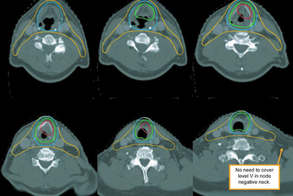
For the unreconstructed right chest wall, Figs. 12.1, 12.2, and 12.3 work like a fast visual atlas. The chapter shows the same contouring solution in coronal, sagittal, and cranial-to-caudal axial views.
The color legend is worth preserving during review: red for PTV, light orange for CTV, blue for level I nodes, light purple for level II, dark orange for level III, green for supraclavicular nodes, and yellow-green for internal mammary nodes. Seeing those structures together is useful because regional nodal irradiation is not one contour. It is a linked set of targets that has to stay anatomically coherent.
The axial sequence in Fig. 12.3 is particularly helpful for superior-inferior continuity. It starts cranially, passes through the axillary transition, and continues along the anterior chest wall. That is the kind of view that helps confirm whether surface coverage, nodal coverage, and thoracic geometry still make sense in the same dataset.
This is also the scenario where the margins from Table 12.1 deserve another look. A 3-5 mm posterior expansion, except at the internal mammary nodes, and a 5-10 mm anterior expansion to include skin can change the contour more than people expect. If the plan will be VMAT or IMRT, the daily 3 mm chest wall bolus should already be part of the setup logic.
The chapter does not add a long narrative beyond referring the reader to the figures, but the visual point is strong enough on its own: chest wall, axillary levels, supraclavicular basin, and internal mammary nodes should be checked as one connected target set, not as separate islands.
Target and nodal volumes for the reconstructed left chest wall with tissue expander
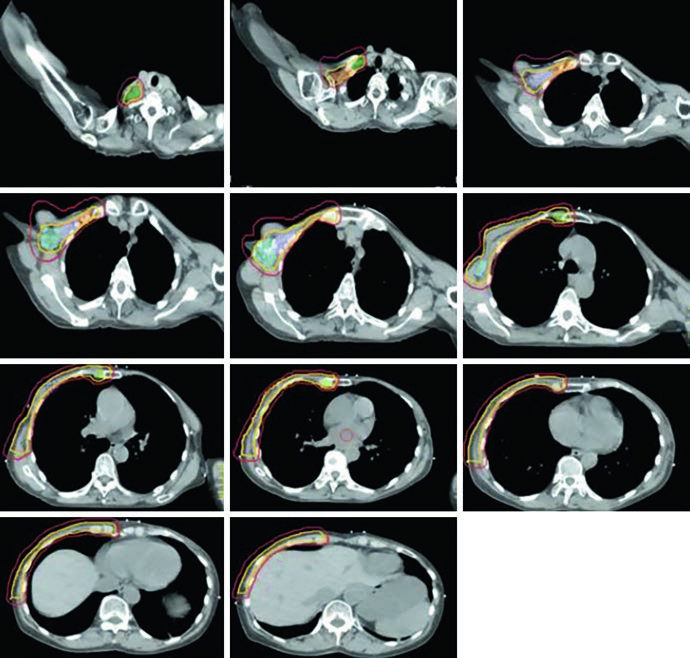
Once the left chest wall has been reconstructed with a tissue expander, the geometry changes and the chapter makes that visible in Figs. 12.4 and 12.5. Coverage is still regional and comprehensive, but now the expander, the heart, and the contralateral breast are part of the visual reading of the case.
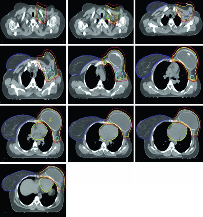
Fig. 12.4 keeps the same contour colors for PTV, CTV, and nodal stations, then adds the heart in yellow and the contralateral breast in dark purple. That matters. In reconstructed left-sided cases, the target cannot be reviewed independently from the structures that need protection while nodal coverage is maintained.
Fig. 12.5 extends that review through cranial-to-caudal axial slices. The tissue expander occupies much of the anterior left hemithorax, and Table 12.3 follows that geometry with a specific rule: inside the implant, PTV D95% should remain at or below 120%. That is not a footnote. It directly affects how hot spots are accepted around the device interface.
The same dosimetric table separates non-DIBH and DIBH goals for ipsilateral lung, heart, and stomach. For the heart, the chapter lists separate mean-dose goals for left breast plus internal mammary coverage at D95% of at least 90% and at least 100%, plus a contingency row for cases in which the primary constraints cannot be achieved. LAD Dmax is 25 Gy, with 35 Gy in parentheses, and stomach mean dose drops from 5 Gy to 3 Gy with DIBH.
This is one of those sections where the table does most of the talking. Once the internal mammary chain is included and the heart sits directly in the planning conversation, the difference between non-DIBH and DIBH stops being theoretical and becomes a practical planning choice.
Conventional 3D conformal planning
The conventional 3D conformal section is short, but it is concrete. The arrangement shown in the chapter uses a medial en face electron beam matched to two opposing lateral tangent fields, then adds dedicated views for supraclavicular coverage and tumor-bed boost geometry.
In Fig. 12.6, the medial en face electron beam is shown in red and matched to two lateral opposing tangents in blue and green. Fig. 12.7 shifts to a coronal view of the supraclavicular field and nodal targets. Fig. 12.8 then shows a 3D boost to the tumor bed: an en face electron field with a custom cutout, shown in blue, encompassing the tumor bed in maroon, clips in light green, and the lumpectomy scar in gray.
The logic stays consistent from the opening pages to the end of the chapter. First, imaging and anatomy are defined. Next, margins and dose goals turn those contours into a plan. Finally, the chapter shows how a conventional 3D solution can still be organized around tangents, a supraclavicular field, and a directed electron boost when that approach is selected.
For the full book-level overview, return to the Target Volume Delineation and Field Setup – Complete Clinical Guide. If you also want the broader disease context from the site, see our coverage of the Lancet projection for global breast cancer cases by 2050.
References from the chapter
The chapter anchors its recommendations in three direct sources: the RADCOMP breast atlas, a three-dimensional mapping analysis of regional nodal recurrences, and a study evaluating low-dose reduction when DIBH is added to VMAT in implant-reconstructed patients receiving regional nodal irradiation.
- MacDonald S et al. RADCOMP Breast Atlas. RTOG Foundation. February 23, 2016.
- DeSelm C, Yang TJ, Cahlon O, Tisnado J, Khan A, Gillespie E, Powell S, Ho A. Three-dimensional mapping analysis of regional nodal recurrences in breast cancer. International Journal of Radiation Oncology, Biology, Physics. 2019;103(3):583-591.
- Dumaine VA, Saksornchai K, Zhou Y, Hong L, Powell S, Ho AY. Reduction in low-dose to normal tissue with the addition of DIBH to VMAT in breast cancer patients with implant reconstruction receiving regional nodal irradiation. Radiation Oncology. 2018;13(1):187.