Radiotherapy equipment packages are meant to keep planning honest: they tie “what you want to deliver” to the minimum set of devices, software and workflows needed to treat safely and consistently.
That framing helps avoid a classic procurement trap: buying the headline machine first and discovering later that imaging, planning, verification and support tools were the real bottleneck. For the full context, see our radiotherapy equipment technical specifications guide.
EBRT and brachytherapy: two practices, two equipment sets
EBRT and brachytherapy rely on different source geometries and workflows, so the equipment list changes with the technique. Still, the publication assumes a comprehensive service that can provide both.
The text distinguishes EBRT (the ionizing source is external to the patient) from brachytherapy (the source is internal or in close proximity to the patient). It also notes that most radiotherapy is delivered as EBRT, with a worldwide ratio of EBRT treatment units to brachytherapy units of more than 9 to 1 (DIRAC, IAEA).
Packages 1, 2 and 3: the planning backbone (Table 2)
Table 2 is the practical map: it defines equipment packages linked to health system capacity, covering both EBRT and brachytherapy.
The packages support needs assessment and a stepwise expansion of capability. The publication states that its detailed technical specifications cover Packages 1 and 2; additional capabilities listed under Package 3 are not specified in this edition.
Related reading: chapter-by-chapter overview.
Table 2. Equipment packages for radiotherapy services (EBRT)
This section of Table 2 lists the EBRT components by package.
| Component | Package 1 | Package 2 | Package 3 |
|---|---|---|---|
| Treatment | Cobalt-60 teletherapy unit (preferably at least one with 100 cm SAD) and/or single-photon energy LINAC; orthovoltage X-ray unit as needed | Package 1 and additional single-photon energy unit(s) and/or multiple energy LINAC with electrons capabilities | Additional multiple energy LINAC unit(s) with electrons and IMRT, VMAT, IGRT, SRS, SBRT capabilities |
| Treatment unit accessories | Laser system for positioning; standard and customized shielding blocks; oncology information system including record and verify system (OIS including RVS); portal imaging | Laser system for positioning; customized blocks with or without MLC; OIS including RVS; EPID | Laser system for positioning; MLC or mini-MLC or cones; OIS including RVS; EPID; in-room MV or kV-imaging (for IGRT); motion management system (for IGRT) |
| Treatment planning | 3D TPS (DICOM-compatible) | 3D TPS (DICOM-compatible) | 3D TPS with additional capabilities (IMRT, VMAT, IGRT, SRS, SBRT) |
| Simulation imaging | Conventional digital simulator with laser system; access to a CT scanner | Package 1 and dedicated CT simulator with moveable laser system | CT simulator with moveable laser system and with additional 4DCT capability; access to MRI and/or PET/CT; fiducial markers |
Table 2. Equipment packages for radiotherapy services (brachytherapy)
This section of Table 2 lists the brachytherapy components by package.
| Component | Package 1 | Package 2 | Package 3 |
|---|---|---|---|
| Treatment unit | HDR remote afterloading unit | HDR remote afterloading unit | HDR remote afterloading unit |
| Source | Cobalt-60 | Cobalt-60 or iridium-192 | Cobalt-60 or iridium-192 |
| Applicators | Cervical (ring applicator set; ovoid applicator set; vaginal cylinders set); endometrial applicator set; transfer tubes | Cervical (ring applicator set including interstitial needles; ovoid applicator set; vaginal cylinders set)*; endometrial applicator set; transfer tubes | Additional CT-MR-compatible cervical intracavitary (ring applicator set; ovoid applicator set; vaginal cylinder set); intracavitary-interstitial (Vienna, Utrecht type); endometrial applicator set; prostate (reusable needles set); transfer tubes |
| Treatment planning | 2D TPS | 2D or 3D TPS | 3D TPS |
| Imaging | Conventional simulator or C-arm fluoroscopic X-ray unit; ultrasound with convex probe | Conventional simulator or C-arm fluoroscopic X-ray unit or CT simulator; ultrasound with convex probe and endorectal probe | CT simulator; access to MRI; ultrasound with convex probe and endorectal probe |
*Applicators that are CT-compatible will need to be procured if treatment planning is 3D CT-based.
CT=computed tomography; EPID=electronic portal imaging device; HDR=high-dose rate; IGRT=image-guided radiotherapy; IMRT=intensity-modulated radiotherapy; LINAC=medical linear accelerator; MLC=multileaf collimator; MR=magnetic resonance; MRI=magnetic resonance imaging; OIS=oncology information system; PET=positron emission tomography; RVS=record and verify system; SAD=source axis distance; SBRT=stereotactic body radiotherapy; SRS=stereotactic radiosurgery; TPS=treatment planning system; VMAT=volumetric modulated arc therapy.
Source: WHO/IAEA Technical Specifications (Table 2).
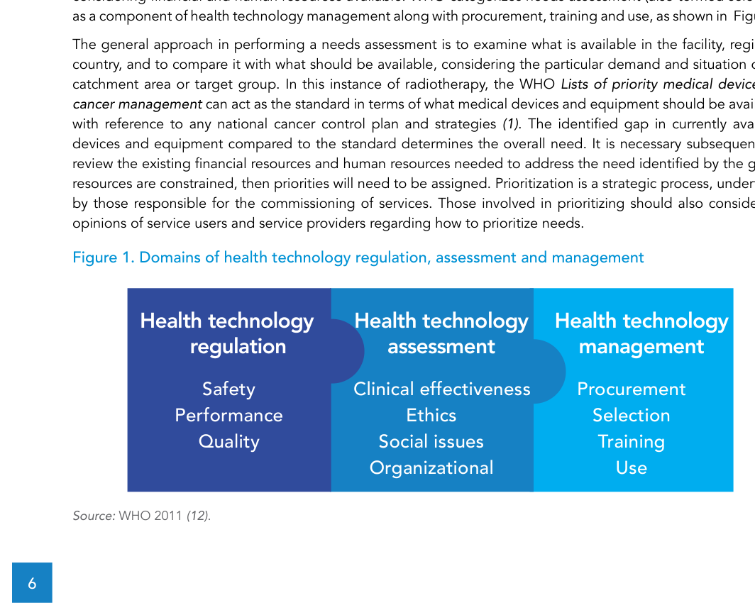
Needs assessment: from “what exists” to “what is needed”
In the WHO definition cited in the text, needs assessment is an examination of what is available versus what should be available for the catchment area, considering financial and human resources.
The workflow is straightforward: document the current inventory; compare it to an agreed standard for what should be in place; quantify the gap; then check financial and staffing constraints to set priorities. The publication emphasizes that prioritization is strategic and should consider the perspectives of both service users and providers.
Service scale: why 1 vs 2 treatment units changes risk
A single external-beam machine department is inherently fragile: a breakdown can halt treatments and there is little headroom for demand growth.
That is why the text advises considering two EBRT treatment units from the outset, with planned expansion. For cobalt-60 teletherapy options, it also notes an operational advantage in procuring one unit with 100 cm SAD and one with 80 cm SAD for resource sparing, referring to the detailed discussion in the relevant section.
Inside EBRT: simulation, planning and delivery
EBRT is a three-step technical process (simulation, treatment planning and treatment delivery with verification), and each step pulls in its own equipment and QA dependencies.
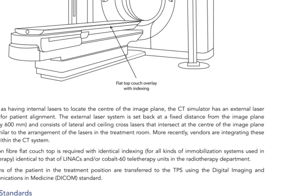
The publication describes fractionated delivery repeated once per working weekday, with courses that may include up to 40 fractions. For simulation, patient imaging in the intended treatment position with immobilization supports delineation of targets and organs at risk and provides reference images for verification; CT simulation adds 3D geometry and tissue mass density information for accurate 3D absorbed dose calculation.
For tumours affected by internal motion (for example, lung tumours over the breathing cycle), the text describes the value of 4DCT (listed under Package 3) and mentions enabling items such as a marker block on the chest, a camera system to monitor the marker and software to sort CT data sets by motion phase.
For planning, the TPS receives images, supports delineation and optimization and provides dose calculation and review tools. For delivery, positioning uses fixed lasers and, when available, in-room imaging; an entire session is described as typically 10–15 minutes, with beam-on time typically 1–2 minutes.
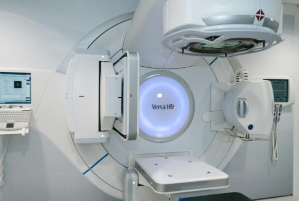
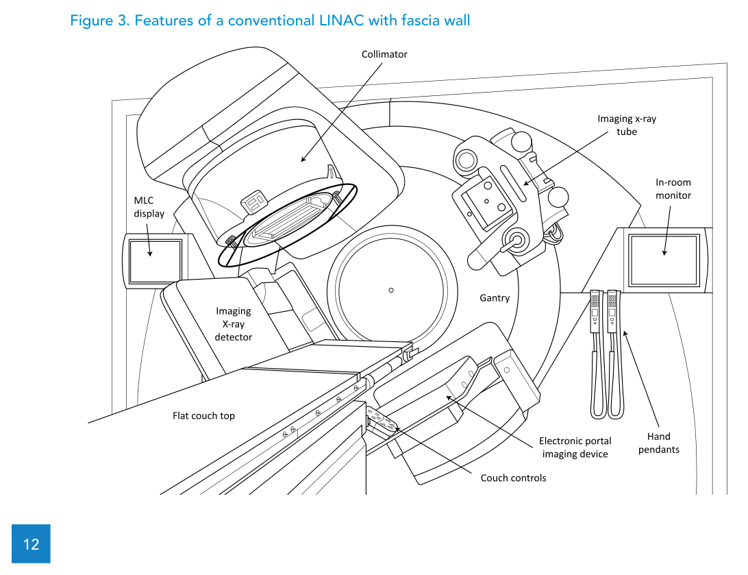
Conventional LINAC and what Package 2 adds
When the publication specifies a LINAC, it focuses on a “conventional” design capable of treating a wide range of sites with photons and electrons, with tools that make 3D-CRT practical.
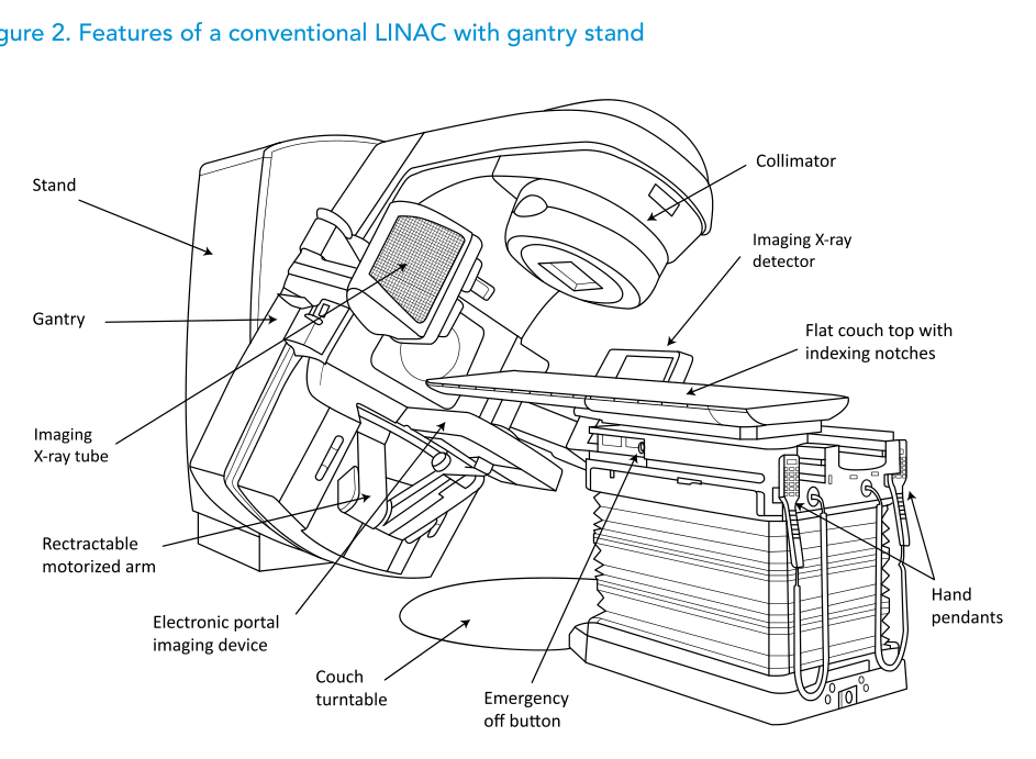
The text describes the conventional rotating-gantry, isocentric design (Figures 2 and 3) and explicitly states that assessing the merits of newer “unconventional” designs is outside its scope.
In line with Package 2, the specification discussed includes both photon and electron modalities, an MLC to enable efficient 3D-CRT practice and an EPID for digital portal imaging in the treatment position. It also notes that the specification can be adapted to the single-energy LINAC described in Package 1, where 6 MV is the standard photon energy choice.
Photon energies: depth-dose and trade-offs (Table 3)
Higher photon energy is not a free upgrade: the publication frames it as a balance between lower entrance dose and higher exit dose, with additional radiation protection implications at higher energies.
For Package 2, a multi-energy LINAC can complement 6 MV with 10, 15 or 18 MV. The text discusses why higher energies can be less suitable when patient separation is small and more suitable when separation is large, and it highlights neutron production at higher energies and the practical choice of limiting the highest energy to 10 MV to minimize neutron protection measures.
It also cites McGinley’s report of neutron dose equivalent ranging from 0.02 mSv/Gy X-ray (10 MV) to 8.3 mSv/Gy X-ray (18 MV) for Varian linear accelerators, and notes that for IMRT techniques neutron dose can be 2–10 times higher, which is one reason given for IMRT/VMAT generally not being practised above 10 MV.
Table 3. Photon beam energies and their depth dose in water
The table compares depth of maximum dose and percentage depth dose at 10 cm depth for common energies and SSD geometry.
| Parameter | Cobalt-60 (80 cm SSD) | Cobalt-60 (100 cm SSD) | 4 MV (100 cm SSD) | 6 MV (100 cm SSD) | 10 MV (100 cm SSD) | 15 MV (100 cm SSD) | 18 MV (100 cm SSD) |
|---|---|---|---|---|---|---|---|
| Depth of maximum dose | 0.5 cm | 0.5 cm | 1.0 cm | 1.5 cm | 2.3 cm | 2.9 cm | 3.2 cm |
| Percentage depth dose at 10 cm depth | 56.4% | 58.7% | 63.0% | 67.5% | 73.0% | 77.0% | 79.0% |
Source: WHO/IAEA Technical Specifications (Table 3). Data from the British Journal of Radiology, Supplement 25, for a 10 cm x 10 cm set field size.
Electron energies: penetration and practical selection (Table 4)
For electrons, the practical question is “how deep can I cover?”, and the text links that directly to R90 and energy selection.
It notes that electron beams are typically offered from 4 MeV to 22 MeV and that departments often select four or five energies. The penetration values (R90) support choosing energies with evenly spaced penetrations. The example specification in the text uses 6, 9, 12 and 15 MeV, delivered with applicators and individualized low-melting point alloy (LMPA) cut-outs.
Table 4. Electron beam energies and their penetration in water
Penetration expressed as R90 (cm) across electron energies.
| Parameter | 4 MeV | 6 MeV | 8 MeV | 9 MeV | 10 MeV | 12 MeV | 15 MeV | 16 MeV | 18 MeV | 20 MeV | 22 MeV |
|---|---|---|---|---|---|---|---|---|---|---|---|
| Penetration expressed as R90 (cm) | 0.9 | 1.7 | 2.4 | 2.7 | 3.1 | 3.9 | 4.7 | 5.0 | 5.5 | 6.3 | 7.0 |
Source: WHO/IAEA Technical Specifications (Table 4). Data from the IAEA Handbook.
MLC, custom blocks and EPID: speed with a complexity bill
Within Package 2, MLC and EPID can streamline delivery and verification, but the publication is explicit about the added complexity in limited-resource settings.
It contrasts customized blocks (manufactured per field in a mould room) with the MLC, which automates beam shaping and can replace blocks in almost all 2D and 3D-CRT situations, while noting there are scenarios (for example, central blocks or “island” blocks) where both may still be needed.
For IMRT/VMAT, the text stresses that specifications extend beyond delivery hardware: they also require additional TPS capabilities for inverse planning and leaf motion calculation, and OIS capabilities to transfer delivery instructions from TPS to the treatment unit.
WHO/IAEA technical specifications: a LINAC checklist
The WHO/IAEA annex reads like a procurement and acceptance checklist: it lays out functional requirements, performance targets, utilities, safety and maintenance expectations to carry into contracts and validation.
The table below highlights a core subset of items from the template, grouped by category.
| Category | Item | Specification (WHO/IAEA template) |
|---|---|---|
| Clinical purpose | Purpose of use | Delivery of megavoltage X-ray and electron beams for external beam radiotherapy (EBRT). |
| Clinical purpose | Functional requirements (overview) | LINAC with gantry, collimator and treatment couch; interface with record and verify system (RVS). |
| Technical requirements | Gantry geometry | Motorized gantry; isocentric design; 100 cm SAD; gantry rotation ±180°; isocentre clearance > 30 cm. |
| Technical requirements | Mechanical isocentre | Maximum diameter ≤ 2 mm for collimator, gantry and couch rotation axes. |
| Technical requirements | Photon field size | Maximum 40 cm x 40 cm and minimum ≤ 4 cm x 4 cm (50% isodose level at isocentre). |
| Technical requirements | Asymmetric jaws | Asymmetric jaw movements for all jaws, crossing the central axis. |
| Technical requirements | Light/radiation field coincidence | ≤ 2 mm. |
| Technical requirements (Package 2) | Integrated MLC | ≥ 80 motorized leaves; maximum 1 cm leaf width at isocentre; interleaf leakage < 4%; leaf position accuracy ≤ 1 mm. |
| Technical requirements | Photon energies | 6 MV with flattening filter. |
| Technical requirements | Photon dose rate | Variable from 50 MU/min up to at least 400 MU/min. |
| Technical requirements (Package 2) | Second photon energy | 10 MV with flattening filter. |
| Technical requirements (Package 2) | Electrons | Energies: 6, 9, 12 and 15 MeV; dose rate ≥ 400 MU/min. |
| Technical requirements | Monitoring and interlocks | Dual internal ionization chambers for monitoring; symmetry ≤ 2% and flatness ≤ 3% (for radiation beams). |
| Infrastructure | Utilities | Three phase electrical power; chilled water; compressed air (as needed); SF6 gas; air-conditioning (six air exchanges per hour). |
| Operation and safety | EPID / portal imaging | Portal imaging (Package 1) or integrated EPID (Package 2) for digital portal imaging and comparison with DRRs. |
| Operation and safety | Fixed lasers | Two lateral cross lasers, one ceiling cross laser and one sagittal line laser (red or green). |
| Operation and safety | Scales and coordinates | IEC 61217 scale convention as at least one option in clinical mode. |
| Commissioning | Requirements for commissioning | Acceptance testing; beam commissioning; reference dosimetry; dosimetry audit; quality control baselines; comprehensive radiation survey. |
| Warranty and maintenance | Warranty | At least 12 months. |
| Warranty and maintenance | Maintenance tasks | 4–8 service days per year (preventative maintenance schedule). |
| Warranty and maintenance | Spare parts availability post-warranty | 10 years minimum. |
| Warranty and maintenance | Estimated lifespan | 10–15 years. |
Source: WHO/IAEA Technical Specifications of Radiotherapy Equipment for Cancer Treatment (Annex 1 – LINAC template).
To connect the checklist back to planning, revisit the full guide and use Table 2 as the dependency map before signing a contract.