Regional lymph node irradiation in breast cancer encompasses treatment of the axillary nodes (levels I through III), supraclavicular nodes, interpectoral (Rotter’s) nodes, and the internal mammary chain. When indicated — particularly after mastectomy with nodal involvement or in locally advanced disease — this approach improves locoregional control and may impact overall survival. Accurate target delineation requires mastery of lymphatic drainage anatomy and meticulous attention to adjacent critical structures.
This article presents practical contouring guidelines for regional nodal irradiation based on the RADCOMP atlas and recommendations from Ho, Dunn, and Powell (Massachusetts General Hospital and Memorial Sloan Kettering Cancer Center), covering both unreconstructed and reconstructed chest wall scenarios. For a comprehensive overview across all anatomical sites, see our complete guide to target volume delineation.
In This Article
Simulation and Patient Positioning
CT simulation follows a standardized protocol: the patient is positioned with both arms raised above the head using breast board immobilization. This position abducts the scapula laterally, moving it away from the treatment field and improving access to axillary volumes. Intravenous contrast is optional but can help identify lymph nodes and vasculature — particularly the subclavian vein, which serves as the anatomical landmark for the transition between axillary levels II and III.
When the breast is intact, the breast borders and lumpectomy scar are wired on the skin before scanning. This surface marking is essential for correlating clinical boundaries with CT images, especially when planning the boost. A common pitfall in practice is failing to wire the scar before the CT — this compromises tumor bed localization on axial slices and may lead to a misplaced boost field.
The scan volume extends from the cricoid cartilage to 5 cm below the clinically marked inferior port edge. Complete inclusion of both lungs is mandatory — an often overlooked detail that can compromise bilateral lung DVH assessment and invalidate the entire plan. Without complete lung apices and bases in the scan, the contralateral $V_{20Gy}$ calculation becomes inaccurate.
Target Volume Definition: CTV and PTV
The clinical target volume (CTV) for regional nodal irradiation encompasses: breast tissue or chest wall as defined by the RADCOMP Breast Atlas, ipsilateral regional lymph nodes, and interconnecting lymphatic drainage routes. In cases with a breast prosthesis, the CTV includes the prosthesis and the chest wall musculature/skin deemed at risk for microscopic disease.
The PTV receives asymmetric margins around the CTV — a critical aspect of this contouring approach that reflects the varying setup uncertainties in each direction:
| Direction | CTV → PTV Margin | Note |
|---|---|---|
| Medial | 3–5 mm | — |
| Lateral | 5–10 mm | Larger uncertainty from respiratory motion |
| Posterior | 3–5 mm | IMN: 0 mm posteriorly (spare lung) |
| Superior / Inferior | 5–10 mm | — |
| Anterior | 5–10 mm | Include skin surface |
Source: Target Volume Delineation and Field Setup, 2nd Edition (Table 12.1)
The internal mammary nodes (IMN) receive zero posterior margin — this protects the underlying lung and is one of the key features distinguishing regional nodal contouring from breast-only treatment. The physician may trim lung inclusion at their discretion, but the reference is to keep lung within the PTV to the minimum necessary for target coverage.
A 3 mm bolus is used daily over the chest wall for all VMAT/IMRT plans. In inflammatory breast cancer, where the skin GTV dose must reach ≥100% of the prescription dose, a thicker bolus (1 cm) may be applied. This ensures adequate skin coverage, which is a primary target in the inflammatory setting. In routine practice, the bolus must be checked daily — displacement or air bubbles significantly reduce the surface build-up effect.
Nodal Levels and Regional Coverage
The PTV for regional nodal irradiation includes all ipsilateral chains: axillary levels I, II, and III, supraclavicular nodes, interpectoral (Rotter’s) nodes, and internal mammary nodes. Each level has a distinct anatomical location and specific clinical relevance, and contouring errors at any level compromise the entire treatment.
Level I lies lateral to the pectoralis minor, encompassing most clinically palpable axillary nodes. It contains the largest number of lymph nodes and is also most susceptible to surgical clip artifacts in patients after partial dissection. Level II sits behind the pectoralis minor — a region easily confused with axillary fat in obese patients — identifying the axillary vein as a superior landmark helps prevent under-contouring at this level.
Level III is medial to the pectoralis minor, near the subclavian vein junction — its contouring requires attention to the transition into the supraclavicular field. The interpectoral (Rotter’s) nodes, located between the pectoralis major and minor, must also be included; despite their small number, omitting them can result in interpectoral space recurrence.
The supraclavicular nodes are included as a contiguous superior volume, while the internal mammary nodes follow the internal mammary artery, typically in the first three intercostal spaces. In practice, IMN contouring tends to be the most controversial component: proximity to the heart (especially on the left side) demands careful balancing between coverage and cardiotoxicity. Nodal recurrence mapping studies, such as those published by DeSelm and colleagues, show that most regional recurrences concentrate in unirradiated stations — reinforcing the importance of including all indicated chains.
Unreconstructed Right Chest Wall
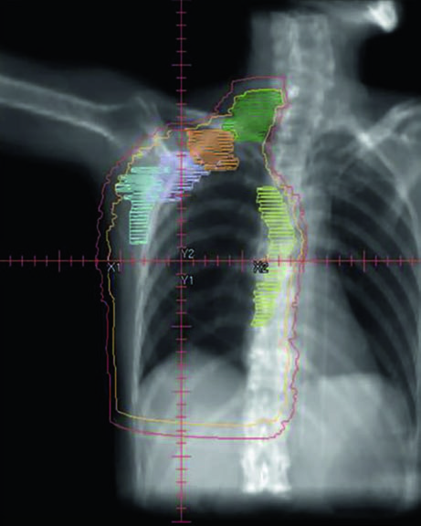
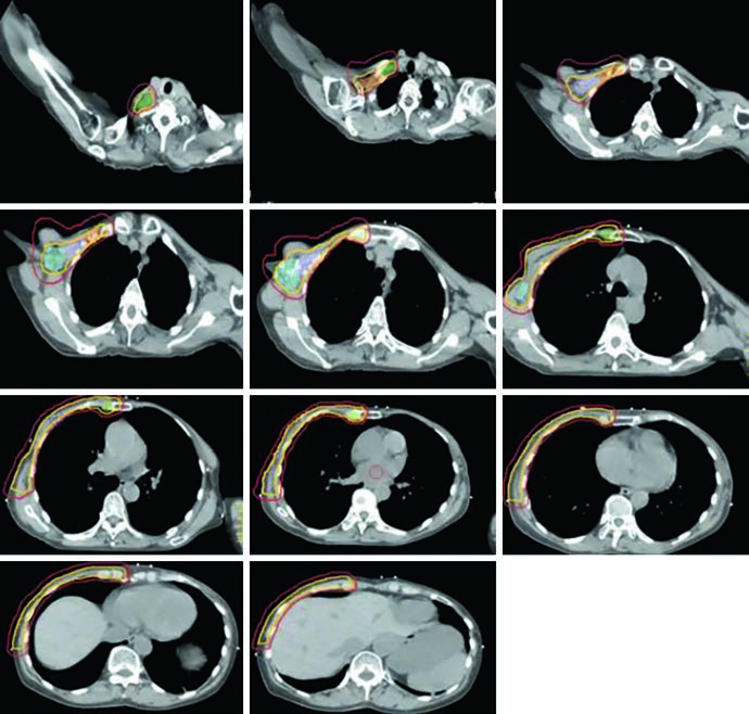
In the post-mastectomy setting without reconstruction, the chest wall constitutes the primary CTV alongside the nodal volumes. Figures 12.1 and 12.2 (coronal and sagittal) and Figure 12.3 (axial slices) illustrate how the contours are distributed: the PTV follows the curvature of the remaining chest wall, with nodal stations contoured contiguously.
Without a prosthesis or expander in the field, planning is more straightforward. The chest wall is relatively flat, allowing tangents with conventional angulation. The main challenge lies in ensuring uniform skin coverage and adequate retrosternal coverage where the IMN reside, without excessive ipsilateral lung dose. The absence of prosthetic volume reduces dosimetric complexity but does not eliminate the need for optimization — especially at the junction between tangential and supraclavicular fields.
Reconstructed (Tissue Expander) Left Chest Wall
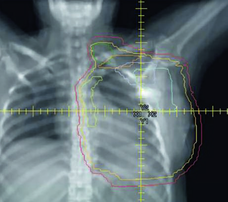
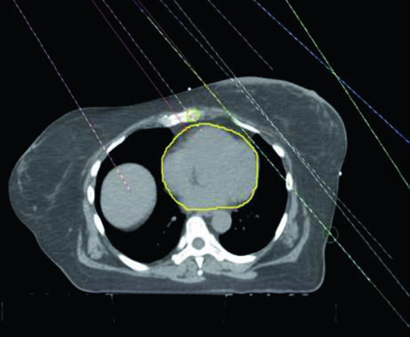
When the patient has tissue expander reconstruction, the planning geometry changes significantly. The expander protrudes the chest wall anteriorly, altering target depths and the spatial relationship with OARs. On the left side, the heart assumes a relatively more anterior position, requiring careful optimization. Figure 12.4 clearly shows the cardiac contour (yellow) in relation to the PTV in the sagittal view — this proximity explains the laterality-specific dosimetric limits.
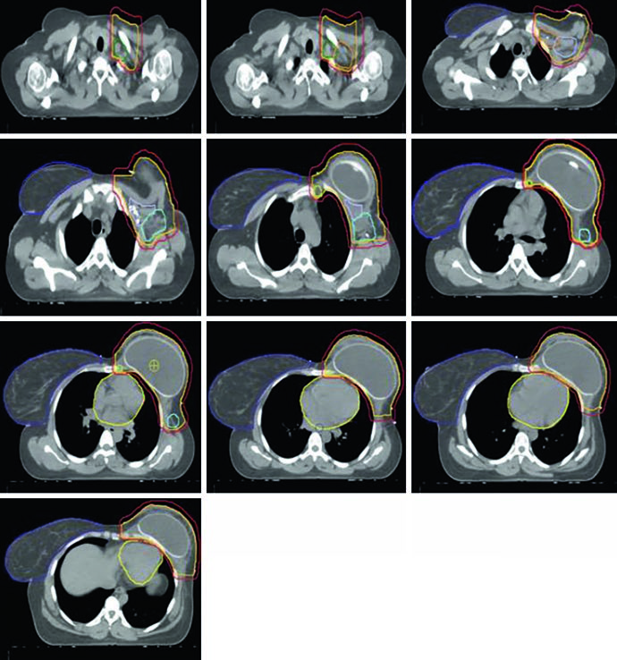
Figure 12.5 shows axial slices for the reconstructed left chest wall. Note how the PTV encompasses the expander bilaterally and how nodal stations maintain their standard contours despite the anatomical alteration. The prosthesis itself is included in the CTV — the IMRT/VMAT criteria specify that the $D_{95\%}$ inside the implant PTV should not exceed 120% of the prescription, an essential limit to avoid damage to the prosthetic material and capsular complications. In practice, hot spots above 120% over silicone or saline expanders can cause accelerated encapsulation and complicate subsequent reconstructive surgeries.
Conventional 3D Conformal Planning
Conventional 3D conformal planning for regional nodal irradiation typically employs a three-beam arrangement: a medial en face electron beam matched to two opposing lateral tangent fields. This classic configuration provides adequate chest wall and IMN coverage with the electron beam, while the tangents treat the lateral breast/chest wall volume and the lower axillary nodes. The main advantage of this technique is its simplicity and reproducibility, although dosimetric homogeneity at the electron-photon junction remains a constant concern.
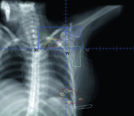
The supraclavicular field is planned separately as an anterior oblique or AP field, covering the level III and supraclavicular nodes. Figure 12.7 shows the coronal view of this field with the nodal targets overlaid — the junction between the supraclavicular field and the inferior tangents is one of the critical points of treatment, where overdose or underdose can occur if the geometry is not precise. The half-beam block technique (asymmetric jaw) minimizes divergence at the junction and reduces the risk of dose overlap.
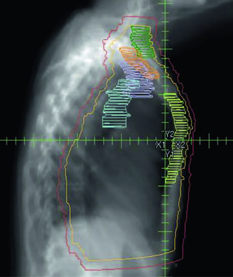
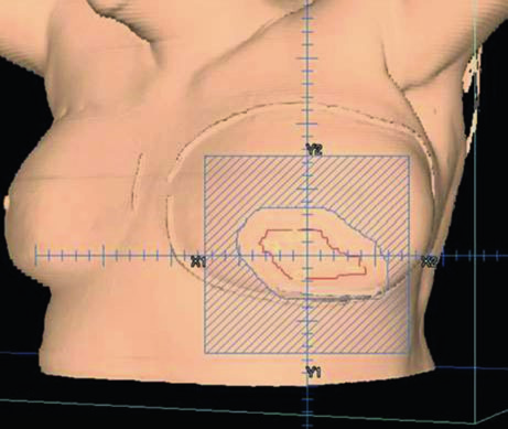
For the tumor bed boost, an en face electron field with a custom cutout is typically used. Figure 12.8 demonstrates this setup in a 3D view: the electron field (blue) encompasses the tumor bed (maroon), surgical clips (light green), and the lumpectomy scar (gray). Electron energy selection depends on bed depth — in practice, 9–12 MeV covers most cases, following the rule that the 80% isodose reaches a depth in centimeters of approximately $E/3$, where $E$ is the energy in MeV.
VMAT/IMRT Dosimetric Guidelines
Dosimetric recommendations for regional nodal irradiation with VMAT follow rigorous criteria for both target coverage and organ-at-risk protection. The standard fractionation is 50 Gy in 25 fractions, maintaining the conventional 2 Gy per fraction scheme.
Target Criteria (50 Gy / 25 Fractions)
| Structure | Parameter | Objective |
|---|---|---|
| PTV | $D_{95\%}$ | ≥ 95% |
| PTV | $V_{95\%}$ | ≥ 95% |
| PTV | $D_{05\%}$ | ≤ 110% |
| IMN | $D_{95\%}$ | ≥ 100% |
The coverage criterion is twofold: both $D_{95\%}$ and $V_{95\%}$ must reach ≥ 95%, ensuring the volume is adequately covered in terms of both point dose and volumetric metrics. The hot spot limit ($D_{05\%}$ ≤ 110%) is standard for breast fields and prevents dose concentrations that can cause skin fibrosis. For the IMN specifically, the $D_{95\%}$ ≥ 100% target is more stringent than the general PTV, reflecting the oncological importance of this nodal station.
Normal Tissue Criteria — VMAT
| Organ at Risk | Parameter | Constraint |
|---|---|---|
| Ipsilateral lung | $V_{20Gy}$ | ≤ 33% |
| Ipsilateral lung | $V_{10Gy}$ | ≤ 68% |
| Ipsilateral lung | Mean dose | ≤ 20 Gy |
| Contralateral lung | $V_{20Gy}$ | ≤ 25% |
| Heart | $V_{25Gy}$ | ≤ 25% |
| Heart | Mean dose | ≤ 9 Gy (left) / ≤ 8 Gy (right) |
| Heart | $D_{max}$ | ≤ 50 Gy |
| LAD | $D_{max}$ | ≤ 50 Gy |
| Contralateral breast (intact) | Mean dose | ≤ 5 Gy |
| Contralateral breast (implant) | Mean dose | ≤ 8 Gy |
| Esophagus | $D_{max}$ | ≤ 50 Gy |
| Thyroid | Mean dose | ≤ 20 Gy |
| Brachial plexus | $D_{max}$ | ≤ 55 Gy |
Source: Target Volume Delineation and Field Setup, 2nd Edition (Table 12.2)
Notice the mean heart dose differs between left breast (≤ 9 Gy) and right (≤ 8 Gy) — this asymmetry reflects the anatomical proximity and the differential risk of cardiotoxicity. The left anterior descending artery (LAD) receives the same $D_{max}$ limit of ≤ 50 Gy as the whole heart. In regional nodal irradiation, lung constraints are more permissive than in breast-only treatment ($V_{20Gy}$ ≤ 33% vs. typically ≤ 20-25% without nodal inclusion), acknowledging the trade-off required to cover the medial nodal volumes.
DIBH and Laterality-Specific IMRT/VMAT Criteria
Deep inspiratory breath hold (DIBH) increases the distance between the chest wall and the heart, significantly reducing cardiac dose. The guidelines distinguish non-DIBH and DIBH criteria, with more restrictive limits for DIBH reflecting the expected geometric gain. The addition of DIBH to VMAT in patients with implant reconstruction has been shown to further reduce the low-dose bath to normal tissue, as published by Dumaine and colleagues.
| Structure | Parameter | Non-DIBH | DIBH |
|---|---|---|---|
| Ipsilateral lung | $V_{20Gy}$ | 30% (33%) | 27% (30%) |
| Ipsilateral lung | $V_{10Gy}$ | 65% (68%) | 60% (63%) |
| Ipsilateral lung | Mean dose | 18 Gy | 18 Gy |
| Contralateral lung | $V_{20Gy}$ | 5% | |
| Heart — left breast | $V_{25Gy}$ | 3% | |
| Heart — right breast | $V_{25Gy}$ | 0.5% | |
| Heart — left + IMN ($D_{95\%}$ ≥ 90%) | Mean dose | 7 Gy (8 Gy) | 6 Gy (7 Gy) |
| Heart — right + IMN ($D_{95\%}$ ≥ 90%) | Mean dose | 4 Gy | |
| Heart — left + IMN ($D_{95\%}$ ≥ 100%) | Mean dose | 8 Gy (9 Gy) | 7 Gy (8 Gy) |
| Heart — right + IMN ($D_{95\%}$ ≥ 100%) | Mean dose | 5 Gy | |
| Fallback (above not achievable) | Mean dose | 10 Gy (12 Gy) | 9 Gy (10 Gy) |
| LAD | $D_{max}$ | 25 Gy (35 Gy) | |
| Contralateral breast (intact) | Mean dose | 6 Gy | |
| Contralateral breast (implant) | Mean dose | 8 Gy | |
| Esophagus | $D_{max}$ | 35 Gy (40 Gy) | |
| Thyroid | Mean dose | 20 Gy | |
| Brachial plexus | $D_{max}$ | 55 Gy | |
| Liver (right side) | Mean dose | 8 Gy (10 Gy) | |
| Stomach | Mean dose | 5 Gy | 3 Gy |
| Cord | $D_{max}$ | 20 Gy | |
Source: Target Volume Delineation and Field Setup, 2nd Edition (Table 12.3). Values in parentheses represent maximum tolerance limits.
This table warrants careful analysis. The mean cardiac dose limits vary according to the level of IMN coverage: when accepting $D_{95\%}$ ≥ 90% for the IMN, cardiac constraints are tighter (7 Gy for left breast non-DIBH). If $D_{95\%}$ ≥ 100% coverage is required, the limit relaxes to 8 Gy. A fallback tier exists — when no limit above is achievable, up to 10 Gy (12 Gy) without DIBH is accepted. In practice, this hierarchical scale allows the dosimetrist to trade IMN coverage against cardiac dose in a stepwise fashion, prioritizing cardiac protection when the anatomy does not cooperate.
The LAD limit with IMRT/VMAT is more restrictive (25 Gy, tolerance 35 Gy) compared to pure VMAT (50 Gy), reflecting the modulation capability to spare this critical structure. The $D_{95\%}$ ≤ 120% criterion inside the implant PTV for reconstructed patients protects against hot spots that could cause capsular contracture or expander failure.
For right-sided treatments, the liver becomes an additional OAR with mean dose ≤ 8 Gy (tolerance 10 Gy) — a detail that applies specifically to regional nodal irradiation, where inferior fields may graze the right hepatic lobe. The stomach is another OAR that differs with DIBH: 5 Gy without versus 3 Gy with breath hold. The spinal cord, with $D_{max}$ ≤ 20 Gy, is rarely dose-limiting but should be contoured in all cases where the supraclavicular field extends medially.
For details on early breast cancer tangent field setup and field-in-field technique, see our dedicated article. When extensive supraclavicular nodal involvement is present, similar nodal coverage concepts apply in other sites — see also our article on lung cancer target delineation, where mediastinal drainage shares similar anatomy.