This article is a detailed look at radiotherapy equipment technical specifications for a superficial/orthovoltage X-ray unit used to deliver kilovoltage beams for external beam radiotherapy (EBRT). It stays focused on what the document specifies: equipment features, depth-dose data, safety, and quality assurance.
For the full context of the series, see the complete guide.
All numeric values and requirement lists are preserved exactly as stated in the source, while the narrative is rewritten for clarity and day-to-day use.
Orthovoltage depth dose in water (Table 14)
The document provides depth-dose percentages in water for orthovoltage X-rays across beam energies expressed as mm Cu HVL, under a defined setup.
The table data correspond to a 5.0 cm x 5.0 cm field size and an SSD of 50 cm using closed applicators.
Table 14. Depth dose of orthovoltage X-rays in water
The table below reproduces the depth-dose data in water for different beam energies (expressed as mm Cu HVL).
| Parameter | 0.5 | 1.0 | 2.0 | 3.0 | 4.0 |
|---|---|---|---|---|---|
| Percentage depth dose at surface | 100% | 100% | 100% | 100% | 100% |
| Percentage depth dose at 2 cm depth | 77.1% | 80.5% | 81.8% | 81.9% | 83.0% |
| Percentage depth dose at 5 cm depth | 44.8% | 49.5% | 52.3% | 53.6% | 55.3% |
Note: The data are for a field size of 5.0 cm x 5.0 cm and SSD of 50 cm with closed applicators. The beam energy is expressed as half-value-layer of copper (Cu HVL).
Source: Data from the British Journal of Radiology, Supplement 25 (Table 14).
Reading the table as it is, the relative dose decreases substantially with depth, and the 2 cm and 5 cm values vary across the listed beam qualities.
Applicable standard (IEC 60601-2-8)
The standard referenced for therapeutic X-ray equipment operating from 10 kV to 1 MV is IEC 60601-2-8, addressing particular requirements for basic safety and essential performance.
The citation in the document is IEC 60601-2-8:2010+AMD1:2015 CSV.
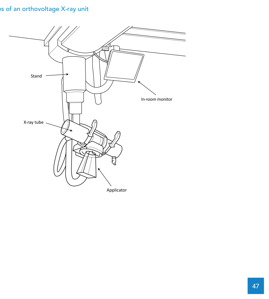
Radiotherapy equipment technical specifications for a superficial/orthovoltage unit
At a functional level, the specification describes a unit that produces collimated kilovoltage X-ray beams for EBRT, including a beam generation system, an adjustable platform, and treatment collimators to support a range of field sizes and beam energies.
Tube, generator, beam qualities, and filters
The X-ray tube must produce energies up to 300 kV and include a cooling system. A minimum of three X-ray energies is required: one low energy (1.0–3.0 mm Al HVL) and two medium energies (1–3 mm Cu HVL).
The generator must include a voltage regulator to operate up to 300 kV. The system must provide a filter for each therapeutic beam and one additional filter that blocks the entire beam for tube warm-up.
The tube current settings must cover a range that allows a constant therapeutic dose-rate to be achieved for each beam energy.
Output monitoring, timers, and tolerances
An internal monitor ionization chamber is required, with response corrected for ambient conditions such as temperature and pressure, or a timer. Dual systems (chamber or timer) are required.
The machine output must be set so that standard reference dosimetry can be maintained within ±2%. The control software must also inhibit radiation if kV or mA exceeds 3% from the selected value.
Radiation must be inhibited if the planned treatment time is exceeded, or if a stop is caused by the secondary timer/monitor chamber.
Mechanical movement and stability
Movement of the tube relative to the floor is specified in multiple directions: vertical, horizontal, and rotation around the column or tube stand, including vertical and axial inclination of the tube by rotation.
A locking mechanism with a brake must ensure the unit will not move during treatment even if power fails, while still allowing the vertical brake to be released in a power failure to remove the patient.
Control console and operational software
The control console must be computerized and include an alternative display inside the treatment room. It must have an on/off removable key, allow selectable kilovoltage settings interlocked to filter interlocks on the treatment head, and provide password-controlled modes.
The console must support backup of system and patient data. Software features listed include: verifying the correct filter and applicator before treatment; displaying digital patient photos (ID and/or setup photos); a complete log of activities and users; patient appointments; password protection; and import/export to an RVS using DICOM RT protocols.
The document also calls out the ability to correctly log cumulative dose in the event of treatment interruption or termination.
Power backup, patient table, and communication
An internal battery or uninterrupted power supply (UPS) is required to retrieve treatment data and to control system shutdown in the event of mains power failure.
A removable patient support table with wheels and brakes is specified, with a flat top surface. Patient monitoring and communication are addressed through two colour CCTV systems (one with pan, tilt and zoom) and a bi-directional audio intercom.
Applicators, field sizes, and custom cut-outs
The specification includes a set of open ended applicators for operation at a fixed focus to source distance (FSD) less than or equal to 30 cm, providing circular field sizes from 2 cm to 8 cm diameter.
It also includes closed applicators for an FSD of at least 50 cm, supporting rectangular field sizes from 6 cm x 6 cm to 20 cm x 20 cm, and explicitly requiring 10 cm x 10 cm and 20 cm x 20 cm square applicators.
A supply of metal sheets is required for creating customized cut-out shapes at the end of the applicator.
For related coverage in the same series, see this article: technical specifications for EBRT equipment.
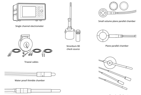
kV dosimetry: additional equipment (Table 15)
The document notes that, alongside the unit itself, the department requires dosimetry, quality control, and radiation safety equipment. It states that items such as a water phantom, electrometer, film, and a survey meter can be used, but that specialized dosimetry equipment is also needed.
Table 15. Additional dosimetry equipment for superficial/orthovoltage X-ray dosimetry
The document lists additional instrumentation for kV dosimetry that complements the department’s routine equipment.
| Item | Description |
|---|---|
| Farmer type chamber | Farmer type chamber, approximate active volume 0.6 cm3, calibration certificate in terms of air kerma in the range of 80–300 kV, TNC or BNC connector, holder for in-air measurements |
| Plane parallel chamber | Plane parallel chamber consistent with IAEA Technical Reports Series No. 398 Table 5, 0.2 cm3 active volume, calibration certificate in terms of air kerma in the range 30–80 kV, TNC or BNC connector. |
| PMMA block set | Set of PMMA blocks, minimum thickness 1 mm, including holder for plane parallel chamber |
| Aluminium plates | Set of aluminium plates, greater than 99% purity, 100 mm x 100 mm in size, total thickness 20 mm, smallest thickness 0.05 mm, including holder |
| Copper plates | Set of copper plates, greater than 99% purity, 100 mm x 100 mm in size, total thickness 10 mm, smallest thickness 0.1 mm, including holder |
| Pinhole applicator | Pinhole applicator for determining the focal spot size |
Source: WHO/IAEA Technical Specifications (Table 15).
Radiation safety and protection
The superficial/orthovoltage tube requires radiation safety and protection measures. The unit is housed in a lead-lined room, with a control room in a neighbouring contiguous room housing the console.
The lead shielding thickness can be calculated using the methodology in IAEA Safety Reports Series No. 47. The document emphasizes shielding in the floor, walls, and ceiling because the beam can be pointed in various directions.
Under the International Basic Safety Standards classification system, the treatment room is designated as a controlled area. Adjacent areas such as the control room and a walkway between the treatment room entrance and control room are also designated as controlled areas.
After installation, a comprehensive radiation survey in the vicinity of the treatment room is required to confirm compliance with local dose limits for staff and members of the public, using a calibrated survey meter.
Safety features listed for the premises include:
- facility access interlock;
- X-ray on and X-ray ready illuminated signs at entrances and within the room;
- ionizing radiation trefoil warning signs at entrances;
- audio visual communication between the treatment room and control room; and
- emergency-off buttons in the treatment room and control room.
Quality assurance and reference dosimetry
To ensure safety and quality in patient treatment, the unit is subject to routine quality control measures, including regular testing of beam dosimetry.
Reference dosimetry is to be performed with calibrated dosimeters, using a code of practice based on dose to water (such as IAEA Technical Reports Series No. 398) or a code of practice based on air kerma (such as IPEM and AAPM codes of practice).
The document points to international recommendations for quality control tests and provides examples of references: IAEA, Setting up a radiotherapy programme: Clinical, medical physics, radiation protection and safety aspects (2008); and Canadian Partnership for Quality Radiotherapy, Technical quality control guidelines for kilovoltage xray radiotherapy machines (2015). Local standards and regulations may also apply and should be complied with.
WHO technical specifications: superficial/orthovoltage X-ray unit
The WHO/IAEA template provides a structured checklist for superficial/orthovoltage unit specifications. The table below summarizes selected items grouped by practical categories.
The selections focus on clinical purpose, technical requirements, infrastructure, safety/standards, and maintenance as described in Annex 7.
| Category | Item | Specification |
|---|---|---|
| Clinical Purpose | Generic name | Superficial/orthovoltage X-ray unit |
| Clinical Purpose | Purpose | Delivery of kilovoltage X-ray beams for EBRT |
| Clinical Purpose | Level of use | Hospital |
| Clinical Purpose | Department | Radiation Oncology Department |
| Clinical Purpose | Functional overview | Collimated kilovoltage X-ray beams for EBRT; includes beam generation system, adjustable platform, and treatment collimators to support a range of field sizes and energies |
| Technical Requirements | X-ray tube | Up to 300 kV with cooling; minimum three energies: one low (1.0–3.0 mm Al HVL) and two medium (1–3 mm Cu HVL) |
| Technical Requirements | Generator | Voltage regulator to operate up to 300 kV |
| Technical Requirements | Filters | Filter for each therapeutic beam + one additional beam-blocking filter for warm-up |
| Technical Requirements | Tube current settings | Range to achieve a constant therapeutic dose-rate for each energy |
| Technical Requirements | Monitor chamber/timer | Internal monitor ionization chamber corrected for ambient conditions or a timer; dual systems required; standard reference dosimetry maintained within ±2% |
| Technical Requirements | Tube movement | Vertical, horizontal, rotation around column/stand; vertical and axial inclination by rotation |
| Technical Requirements | Brake/locking | Must not move during treatment even with power failure; allow vertical brake release during power failure to remove the patient |
| Technical Requirements | Control console | Computerized console with alternative in-room display; removable key; kV selection interlocked to filter interlocks; password-controlled operation modes; backup of system and patient data |
| Technical Requirements | Software features | Check filter/applicator; inhibit radiation if kV or mA exceeds 3%; inhibit if planned time exceeded or secondary stop; display digital photos; complete logs; appointments; cumulative dose logging for interruptions; password protection; import/export to an RVS via DICOM RT protocols |
| Technical Requirements | Battery/UPS | Retrieve treatment data and control shutdown during mains failure |
| Technical Requirements | Patient support table | Removable with wheels and brakes; flat top surface |
| Technical Requirements | CCTV/intercom | Two colour CCTV systems (one with pan/tilt/zoom) and a bi-directional audio intercom |
| Technical Requirements | Open ended applicators | Fixed FSD <= 30 cm; circular fields 2–8 cm diameter |
| Technical Requirements | Closed applicators | FSD >= 50 cm; rectangular fields 6 cm x 6 cm to 20 cm x 20 cm; must include 10 cm x 10 cm and 20 cm x 20 cm square applicators |
| Technical Requirements | Custom cut-outs | Metal sheets to create customized cut-out shapes at the end of the applicator |
| Infrastructure | Utilities | Single-phase electrical power and air-conditioning |
| Safety/Standards | International standards | IEC 60601-1:2005+AMD1:2012; IAEA GSR Part 3 (2014); IEC 60601-2-8:2010+AMD1:2015 CSV |
| Safety/Standards | Regulation example | USA: 21CFR892.5900 X-ray radiation therapy system; local radiation safety regulations may apply |
| Maintenance | Warranty | At least 12 months |
| Maintenance | Preventative maintenance | Approximately 4 service days per year, per manufacturer schedule |
| Maintenance | Estimated lifespan | 10–15 years |
Source: WHO/IAEA Technical Specifications of Radiotherapy Equipment for Cancer Treatment (Annex 7).
To keep the broader structure in view, return to the complete guide and continue through the related articles in the series.