In esophageal cancer, target volume delineation and field setup start at simulation, not at the final planning screen. This chapter lays out a practical CT-based workflow for IMRT and 3D-CRT, then moves through motion management, nodal coverage, and volume margins for cervical, thoracic, and gastroesophageal junction disease. For the broader series context, see the Target Volume Delineation and Field Setup – Complete Clinical Guide.
General principles of planning and target volume delineation
The standard described here is CT-based planning with conformal techniques. IMRT and 3D-CRT both rely on multiple beam angles and allow different levels of dose conformality, but neither works well without careful contouring of target volumes, normal tissues, and organs at risk, followed by dose-volume histogram review during plan evaluation.
The anatomic course of the esophagus explains why that discipline matters. The organ begins in the neck at the lower border of the cricoid cartilage, anterior to the sixth cervical vertebra, then descends through the mediastinum, crosses the diaphragm, and enters the abdomen. A useful plan therefore requires familiarity with neck anatomy, the brachial plexus, mediastinum, lungs, heart, spinal cord, and normal esophagus, and the authors point to a thoracic contouring atlas as a practical reference.
Simulation
The preferred simulation position is with the arms above the head. That choice opens more beam arrangements and avoids unnecessary traversal through the upper extremities. For distal esophageal and gastroesophageal junction tumors, the chapter recommends explicit management of respiratory motion with four-dimensional CT, respiratory gating, or breath-hold techniques, because motion affects how confidently the internal target can be expanded.
The workflow also includes a simple reproducibility measure: patients with distal or gastroesophageal junction tumors should remain nil per os for at least 2 to 3 hours before simulation and before each treatment. The point is to limit day-to-day variation from gastric or bowel gas. When IMRT is used, intravenous contrast at simulation can improve nodal field definition.
Esophageal subdivisions
Using a standard 40 cm distance from the incisors to the gastroesophageal junction, the chapter divides the esophagus into workable clinical segments. The cervical esophagus extends to roughly 15 to 20 cm. The upper or proximal thoracic esophagus runs from 18 to 20 cm to about 25 cm. The mid or distal thoracic segment spans 25 cm to 30 to 32 cm. The abdominal esophagus covers 30 to 32 cm to 40 cm. That framework helps organize endoscopic findings and keeps elective nodal coverage aligned with the actual level of disease.
The authors recommend approaching contouring by anatomic subgroup: upper and mid esophageal tumors, thoracic esophageal tumors, and gastroesophageal junction tumors. Tumors that cross more than one subdivision can follow the guidance for every involved subset. Regardless of primary location, the entire lungs should be contoured for proper DVH analysis. Upper esophageal tumors also call for contouring of the brachial plexus and larynx. Lower tumors shift attention toward the heart, liver, kidneys, stomach, and adjacent bowel.
Esophageal cancer target delineation
The chapter uses GTV, CTV, and PTV, but the institutional workflow described by the authors routinely inserts an ITV between the GTV and the CTV. That ITV captures internal motion seen on 4DCT. It is then expanded to CTV and finally to PTV. In practice, that extra step is especially valuable for distal esophageal and gastroesophageal junction tumors, where respiratory motion is not trivial.
Physicians are advised to define the GTV with reference to CT, PET, upper endoscopy, and endoscopic ultrasound. Endoscopic ultrasound improves assessment of depth of invasion and can help classify small peri-esophageal lymph nodes that remain difficult to sort out on CT or PET alone. If the tumor lies above the carina, bronchoscopy is recommended to rule out a tracheoesophageal fistula, because that finding may delay radiotherapy.
ITV, CTV, and PTV margins
The standard ITV-to-CTV expansion is 1 cm radially to encompass peri-esophageal lymph nodes and 3 to 4 cm in the superior-inferior direction along the esophageal mucosa to account for submucosal spread and possible skip lesions. Where the expansion overlaps the heart or uninvolved liver, the chapter allows that margin to be limited to 0.5 cm, provided motion management is adequate.
Distal esophageal and gastroesophageal junction cases need a more selective caudal approach. A full 4 cm caudal margin would bring in large volumes of stomach or abdominal viscera, so the recommendation is 2 cm along clinically uninvolved gastric mucosa. The exception is preoperative-intent treatment at doses of 4500 cGy or less, where a gastric margin of 4 cm or more may be appropriate, particularly with substantial gastric extension. Uninvolved vertebral bodies and kidneys are excluded from the CTV. Grossly involved lymph nodes can receive a GTV-to-CTV margin of 0.5 to 1.0 cm, and gross peri-esophageal nodal disease should be covered by at least 1 cm cephalad beyond the involved nodes. The chapter recommends 0.5 cm from CTV to PTV, while acknowledging that these numbers can be adjusted according to the motion assessment technique and confidence in disease extent.
Elective nodal coverage by tumor location
Elective nodal coverage follows the level of the primary. Cervical and proximal thoracic tumors include the bilateral supraclavicular nodal basins. Their cranial border is the lower edge of the cricoid cartilage, and the anterior, posterior, and lateral boundaries are defined by the sternocleidomastoid muscle. Proximal thoracic tumors also include mediastinal lymph nodes in addition to peri-esophageal nodes, encompassing the entire trachea, levels 2 and 4, with extension toward the sternum and clavicular heads to cover level 3.
Distal tumors should include the celiac nodes. The chapter defines them precisely: the right boundary is the lateral aspect of T12, the left boundary extends 0.5 to 1 cm beyond the lateral aspect of the aorta, the posterior boundary is the vertebral bodies, and the anterior boundary is the pancreas. Elective inclusion of superior mediastinal stations is not required for distal tumors apart from overlap with the cranial expansion already described. For gastroesophageal junction tumors, the CTV should also include para-aortic and gastrohepatic ligament nodes in a volume bounded by the liver on the right and the stomach on the left.
Gastroesophageal junction tumors and the Siewert-Stein classification
When a gastroesophageal junction tumor overlaps the gastric cardia substantially, the site of origin may appear gastric rather than esophageal. The chapter addresses that problem with the Siewert-Stein classification. Type I lesions have an epicenter 1 to 5 cm above the junction. Type II lesions extend from 1 cm proximal to 2 cm distal to the junction. Type III lesions have an epicenter 2 to 5 cm below the junction. The text treats Siewert type II as a reasonable cutoff for esophageal cancer and notes that the eighth edition of the AJCC staging system now defines esophageal tumors as those whose epicenter extends no more than 2 cm into the gastric cardia.
For Siewert type II tumors, some or all of the splenic hilum and greater curvature nodal region may be included. The chapter also notes that prevailing gastric cancer guidelines support consideration of diagnostic laparoscopy, J-tube placement, preoperative chemoradiation, or postoperative chemoradiation.
Summary recommendations by esophageal segment
Table 14.1 condenses the contouring recommendations into four clinical scenarios. It brings together the segment definition, ITV-to-CTV expansion, CTV-to-PTV margin, elective nodal coverage, and dose approach described by the authors.
Table 14.1. Summary of contouring recommendations for esophageal cancer
| Subdivision | Definition | ITV to CTV margin | CTV to PTV margin | Elective nodal coverage | Dose |
|---|---|---|---|---|---|
| Cervical | Incisors to approximately 15-20 cm | 3 cm superior and inferior along mucosa, with 1 cm radial margin | 0.5 cm | Periesophageal, supraclavicular, and ± anterior mediastinal | 50.4 Gy in 1.8 Gy per fraction, with consideration of dose escalation to 60-70 Gy for SCC |
| Upper thoracic | From 18-20 cm to approximately 25 cm | 3 cm superior and inferior along mucosa, with 1 cm radial margin | 0.5 cm | Periesophageal, supraclavicular, and ± anterior mediastinal | 50.4 Gy in 1.8 Gy per fraction |
| Lower thoracic | From 25 cm to approximately 37 cm | 3 cm superior and inferior along mucosa, with 1 cm radial margin | 0.5 cm | Periesophageal | 50.4 Gy in 1.8 Gy per fraction for definitive treatment; 41.4-50.4 Gy in 1.8 Gy per fraction for preoperative treatment |
| Abdominal (gastroesophageal junction) | From approximately 37 to 42 cm | 3 cm superior along esophageal mucosa and 1-2 cm inferior along gastric mucosa for 50.4 Gy; with preoperative-intent doses (≤4500 cGy), a gastric margin of ≥4 cm may be appropriate | 0.5 cm | Periesophageal, gastrohepatic ligament (paracardiac and left gastric stations), celiac axis, and ± splenic hilum | 50.4 Gy in 1.8 Gy per fraction for definitive treatment; 41.4-50.4 Gy in 1.8 Gy per fraction for preoperative treatment |
Source: Target Volume Delineation and Field Setup, 2nd Edition (Table 14.1)
Clinical examples from the chapter
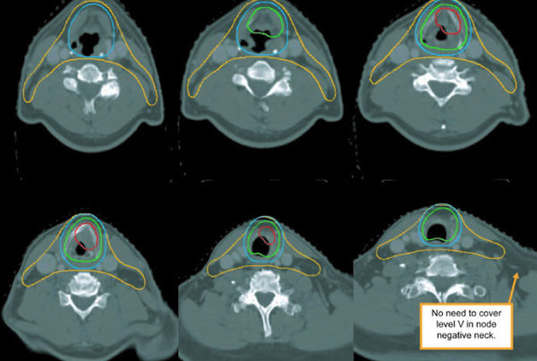
The figures show how the chapter translates rules into actual contours. Figure 14.1 presents a 69-year-old patient with squamous cell carcinoma of the cervical or upper thoracic esophagus. PET demonstrates an avid primary and mildly avid paratracheal nodes, while endoscopy describes an ulcerating submucosal mass 15 to 23 cm from the incisors. The final contour set includes the brachial plexus, larynx, esophageal GTV, nodal GTV, CTV, a 54 Gy PTV, and a 60 Gy PTV. The continuation image adds a practical reminder: elective bilateral supraclavicular coverage is included, but the CTV does not extend above the cricoid.
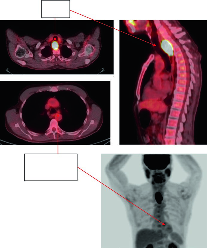
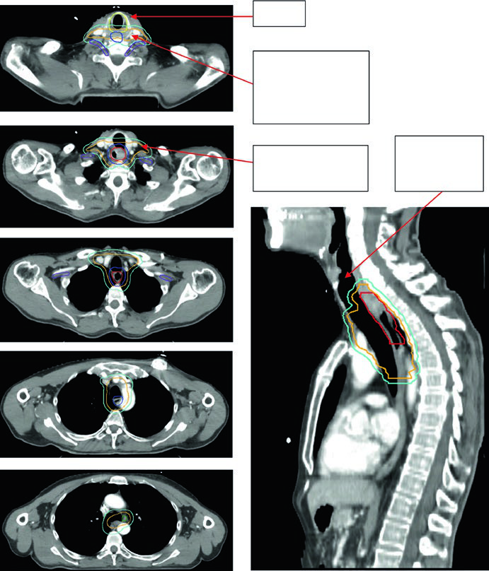
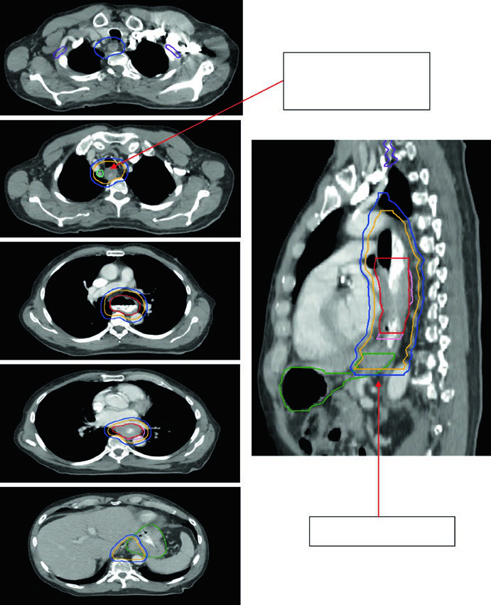
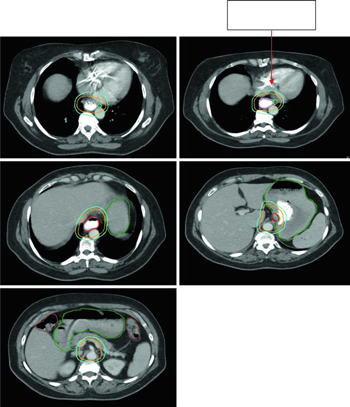
Figure 14.2 follows an 81-year-old patient with lower thoracic esophageal adenocarcinoma staged as uT3N1. PET shows the primary and a level 4R node. Endoscopy shows a partially obstructing circumferential adenocarcinoma 31 to 35 cm from the incisors, and endoscopic ultrasound supports T3 disease with a suspicious 4R node. The continuation figure sharpens two numbers that matter during contour review: a 0.5 cm GTV-to-CTV expansion for the nodal disease and 3 to 4 cm of inferior coverage.
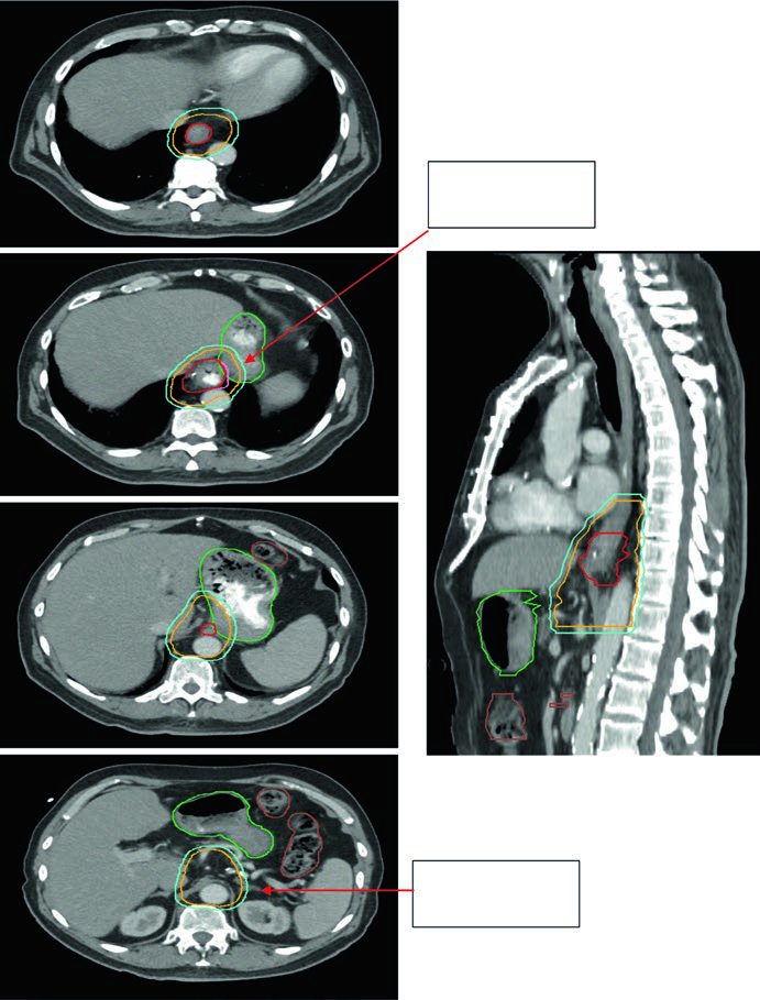
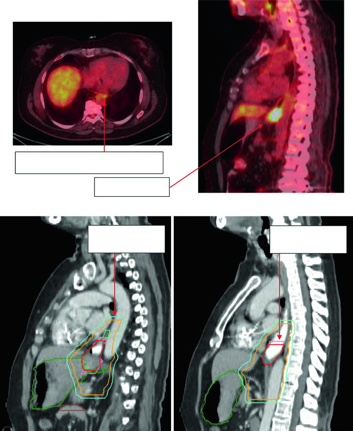
Figures 14.3 and 14.4 shift to gastroesophageal junction disease. Figure 14.3 shows a 75-year-old patient with uT3N0 gastroesophageal junction adenocarcinoma in whom the CTV extends into the proximal stomach and down to the celiac axis. Figure 14.4 then shows a 59-year-old patient with uT3N2 gastroesophageal junction adenocarcinoma located 36 to 40 cm from the incisors, with a PET-avid primary and paraesophageal node. The sagittal planning CT demonstrates movement of the GTV within the ITV, 3 to 4 cm of coverage above the ITV, and deliberate inclusion of the paraesophageal node within the CTV.
The chapter ends on a practical note rather than a theoretical one. Follow the mucosal axis, account for motion, adapt elective nodal coverage to the level of the primary, and avoid automatic distal expansion into uninvolved stomach or abdominal viscera. To compare that logic with the rest of the disease-site series, return to the complete guide to target volume delineation and field setup.