Planning for early breast cancer in this chapter rests on three technical demands: well-constructed tangents, homogeneous dose across the breast, and disciplined definition of the surgical bed whenever a boost or APBI is being considered. The authors move through the full workflow, from mammography, ultrasound, and pathology review to simulation, positioning, target contouring, and heart and lung assessment. For broader context, read our complete guide to target volume delineation and field setup.
Early breast cancer: general planning principles
The chapter identifies three-dimensional conformal radiation therapy with appropriate compensation as the standard adjuvant technique. That compensation can come from a field-in-field approach and, when needed, from mixed-energy beams, with one practical goal: a homogeneous dose throughout the breast tissue. The same section states that the highest level of evidence supports hypofractionated whole-breast irradiation, so dose uniformity is framed as a core planning requirement rather than a cosmetic refinement.
This opening section is direct for a reason. The chapter does not separate contouring from planning, because homogeneous breast coverage depends on both the geometric definition of the volume and the way the tangents are compensated. When 3D CRT and IMRT are both mentioned as workable techniques, the text is not making a platform argument. It is saying that whatever technique is chosen must preserve the same operational endpoint: reliable breast coverage without losing control of the dose that reaches the heart and lungs.
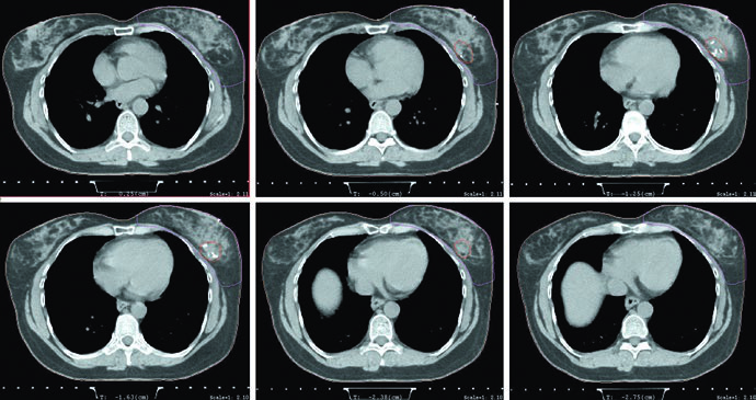
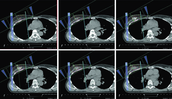
The planning figures make that point concrete. The supine example uses tangents with a field-in-field technique for homogeneity and a small MLC block for cardiac shielding. The caption also gives the prescription plainly: 42.4 Gy at 2.65 Gy per fraction, followed by an electron boost to the lumpectomy cavity to 10 Gy at 2.5 Gy per fraction. In other words, compensation is not presented as a late polishing step. It is part of the standard technique from the start.
The scope is disciplined as well. The chapter stays focused on the early-breast setting instead of drifting into more complex regional or locally advanced scenarios. That narrow focus matters. It keeps the reader anchored to the breast, the lumpectomy cavity, and the setup details that make daily treatment reproducible.
Imaging, surgery, and pathology before simulation
Before radiation planning starts, the chapter calls for careful review of the physical examination, preoperative imaging, and pathology. Every patient should have a mammogram at diagnosis, and ultrasound is commonly added. MRI has limited indications in early-stage disease, but if MRI images are available they should be reviewed before planning to support whole-breast margins and accurate localization of boost and APBI targets.
The surgical and pathology sequence is just as structured. Image-guided biopsy generally confirms the diagnosis. For ductal carcinoma in situ, the cited surgical approach is lumpectomy or segmental excision alone. For early invasive disease, lumpectomy with sentinel lymph node biopsy is recommended. Pathology review then becomes essential because the chapter anchors margin adequacy to specific criteria: no tumor on ink for invasive disease and 2 mm for pure DCIS, following the 2016 SSO-ASTRO consensus guideline named in the text.
Surgical clips receive a practical, high-value note. The authors prefer, although do not require, that the surgeon place clips at the time of surgery to help define the tumor bed and support radiographic localization before treatment delivery. Their usefulness becomes even greater if APBI is under consideration. Without clips, the planner has to lean more heavily on seroma, breast tissue asymmetry, and comparison with the opposite breast.
This is why the chapter keeps insisting on review of all available imaging before planning. The lumpectomy bed is not meant to be guessed from the simulation CT alone. The source text explicitly points the reader back to mammogram, ultrasound, and MRI when available. Target definition begins before the first contour is drawn.
Simulation CT, supine positioning, prone positioning, and DIBH
For whole-breast radiation planning, the chapter recommends CT with slice thickness of 3 mm or less, performed either supine or prone. For APBI, the requirement tightens: 1.5 to 2 mm slices through the lumpectomy cavity may improve cavity delineation. That is a practical imaging statement, not a technical ornament. Better visualization of the cavity supports more credible CTV and PTV construction.
In the supine setup, the patient should be placed on a breast board with the arms above the head. For left-sided breast cancer, the chapter advises considering deep inspiration breath hold in order to reduce heart dose. The wording matters. DIBH is not turned into a ritual requirement for every left-sided case, but it is clearly brought into the decision pathway whenever cardiac sparing can be improved through a reproducible breath-hold technique.
Prone positioning is discussed in a similarly practical way. Patients with pendulous breasts may benefit because the breast separation is reduced and tissue homogeneity can improve, which in turn may reduce acute toxicity. The text also notes that prone positioning lowers lung dose and may help with heart avoidance. Then it adds the warning that makes the guidance useful: when the tumor bed abuts the chest wall, the heart may paradoxically move closer to the treatment field. Prone positioning is therefore presented as a useful option, not an automatic upgrade.
The mechanical side of prone setup is also explicit. The patient should be placed on a dedicated prone breast board, and comfort matters because reproducibility depends on it. Patients with orthopedic injuries involving the back or neck may not be good candidates. That short comment keeps the chapter grounded in daily treatment reality. A clever geometry is not a better setup if the patient cannot maintain it reliably.
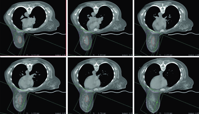
The planning figures reinforce the same message. The prone example uses tangents with a field-in-field technique, the same prescription of 42.4 Gy at 2.65 Gy per fraction, and a mini-tangent photon boost to 10 Gy at 2.5 Gy per fraction. The caption then adds a useful geometric detail: the posterior edge of the field should include part of the pectoralis muscle. If you want to extend that reasoning from the breast alone to nodal basins, our related article on regional nodal irradiation for breast cancer is the next step.
Tumor bed boost and selective use of APBI
The chapter defines the role of boost in one sentence with major clinical consequences. A boost to the tumor bed further reduces local recurrence risk, but it may be omitted in low-risk patients. The point is not to turn the decision into a formula. It is to establish the planning baseline: boost has recognized value, yet omission can be reasonable in a selected low-risk group.
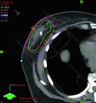
When boost is used, planning most often relies on an en face electron beam. Beam energy should be chosen according to the depth of the tumor bed plus a margin, without extending beyond the anterior surface of the pectoralis muscles. The boost figure turns that rule into something visible by showing selection of 12 MeV to cover the 90% isodose line to the anterior surface of the pectoralis muscle. For a deep tumor bed, the chapter allows a practical alternative: mini-tangents.
APBI is then positioned carefully. It is not yet called the standard of care, but it is described as an acceptable alternative for selected low-risk patients with unifocal disease. The text stops there, and that restraint is part of its value. Instead of overselling APBI, the chapter marks out the specific setting in which partial-breast treatment can be justified.
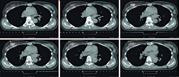
The figure and the table explain how that target is built. The lumpectomy cavity should include seroma, clips, and notable glandular changes. Table 11.1 recommends a 1.0 to 1.5 cm expansion for lumpectomy CTV and a 0.5 to 1.0 cm margin for lumpectomy PTV based on setup uncertainty and expected patient motion. The APBI figure then shows a typical example: a 1.5 cm expansion around the cavity, excluding pectoralis muscle, rib, and chest wall, without extending outside the contoured breast tissue and without reaching the skin, staying 5 mm from the patient surface. PTV is then generated by an approximately 5 mm expansion around the CTV, depending on institutional setup uncertainty.
That pairing of figure and table is useful because it prevents two common planning mistakes. One is automatic expansion without checking where breast tissue actually ends. The other is making the PTV artificially neat and forgetting that the chapter explicitly allows it to extend beyond the patient surface and into pectoralis or chest wall muscles when that reflects setup margin. For APBI, the source text asks for both anatomic discipline in the CTV and geometric honesty in the PTV.
The APBI planning figure closes the loop. It uses mini-tangent photon fields together with an en face electron field. Nothing in the chapter treats APBI as disconnected from whole-breast logic. The volume changes, but the same demands remain in place: field orientation has to match the postoperative anatomy, and beam choice has to respect depth and target location.
Target definition for the breast and lumpectomy cavity
The breast target is built from mandatory clinical reference. The breast may be wired or marked clinically at the time of CT, and the contour should include all glandular breast tissue. The anatomic borders are specific: cranially, below the head of the clavicle and at the insertion of the second rib; caudally, where breast tissue is lost; medially, the edge of the sternum without crossing midline; laterally, the midaxillary line with recognition that ptosis affects perception of that edge; anteriorly, the skin or a few millimeters from the skin for dose reporting; posteriorly, the pectoralis and chest wall muscles, while excluding the muscles themselves and the ribs.
Suggested target volumes for 3D planning in early breast cancer
Table 11.1 is the operational core of the chapter. It defines what belongs inside each target, where the anatomic borders should stop, and when an expansion becomes unacceptable.
| Target volume | Definition and description |
|---|---|
| Breast | Clinical reference is required for breast tissue delineation. The breast may be wired or borders may be placed clinically at the time of CT. The contour should include all glandular breast tissue. The cranial border should be below the head of the clavicle and at the insertion of the second rib. The caudal border is defined by the loss of breast tissue. The medial border is at the edge of the sternum and should not cross midline. The lateral border is the midaxillary line, although ptosis can shift how that border is perceived. The anterior border is the skin or a few millimeters from the skin surface when the purpose is dose reporting. The posterior border is the pectoralis muscles and chest wall muscles. The volume should not include those muscles or the ribs. In very medial or very lateral situations, the borders may extend slightly beyond these definitions to maintain an adequate margin on the lumpectomy cavity. |
| Lumpectomy cavity | Seroma, surgical clips, and obvious differences in glandular breast tissue should be included. Comparison with the contralateral breast can help, especially when fluid and clips are absent. All available imaging studies should be reviewed before planning to assist with this contour. This volume should not extend outside the breast tissue. |
| Lumpectomy CTVa | This is the lumpectomy cavity with a 1.0 to 1.5 cm expansion. It should not extend outside the body or into the pectoralis muscles and chest wall muscles. |
| Lumpectomy PTVa | This is the lumpectomy CTV with a margin based on setup uncertainty and predicted patient motion, generally 0.5 to 1.0 cm. This volume may extend outside the patient surface and into the pectoralis muscles or chest wall muscles. Adjustments may be needed for dose-reporting purposes. |
Source: Target Volume Delineation and Field Setup, 2nd Edition (Table 11.1)
a For APBI only; in whole-breast irradiation, the lumpectomy cavity alone is the boost target.
This degree of detail explains why the chapter insists on clinical reference for contouring. The breast is not a structure that should be outlined from window settings alone. Glandular distribution, inferior and lateral ptosis, and the relationship to the sternum and midaxillary line require a clinical reading of the patient at the time of simulation. The text also allows slight extension beyond these border rules in very medial or very lateral cases to ensure an adequate margin on the lumpectomy cavity. The anatomic rule exists, but it is not meant to compromise surgical-bed coverage.
The lumpectomy cavity follows a different logic. Seroma, clips, and obvious glandular differences belong in the volume. If those signs are subtle or absent, the chapter recommends comparing with the contralateral breast and revisiting prior imaging. What it clearly discourages is a vague cavity contour drawn from memory or soft hints on CT. The boost target, and in APBI the foundation of both CTV and PTV, has to be defensible.
The chapter also draws a firm distinction between whole-breast treatment and APBI. In whole-breast irradiation, the lumpectomy cavity alone is the boost target. In APBI, target expansion becomes part of the treatment definition, with dedicated lumpectomy CTV and PTV. That difference is easy to overlook, but it shapes the entire geometry of the plan.
Heart, lungs, and the finer points of cardiac contouring
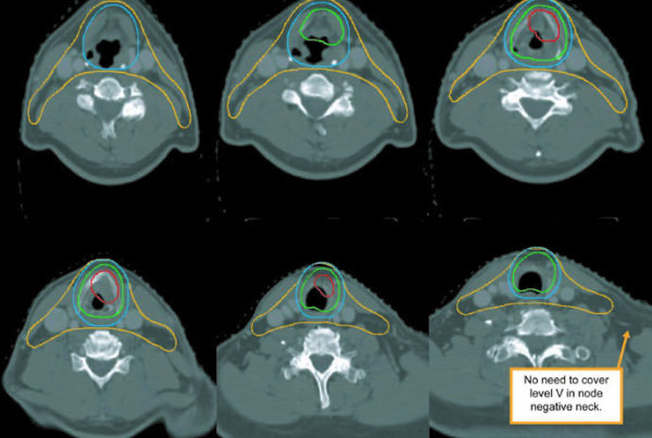
In every case, the organs at risk should include heart and lungs. The heart should be contoured superiorly to the bifurcation of the pulmonary artery, and the contour should include the pericardium and the epicardial fat that lies between the heart muscle and the pericardium. Pericardial fat outside the pericardium does not need to be included. The corresponding figure shows that distinction clearly and removes a common source of inconsistency between planners.
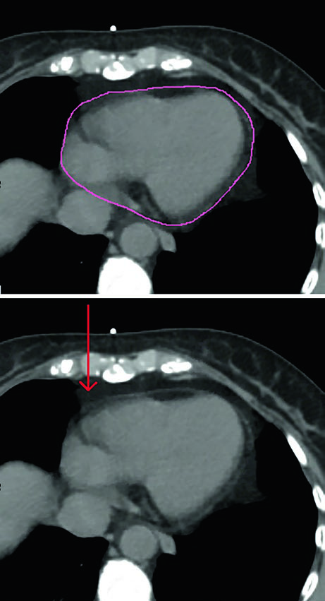
The chapter also clarifies hierarchy. The strongest evidence for cardiac avoidance still supports reduction of mean heart dose. At the same time, the authors note that emerging data suggest potential importance of the dose to the left anterior descending artery and the left ventricle. Those structures may therefore be contoured using the published atlases by Feng et al. and Duane et al., exactly as listed in the chapter references.
That combination of a well-established metric and more detailed substructure review is one of the more mature features of the chapter. It does not replace a robust endpoint with a newer one prematurely. Instead, it allows the team to add precision when needed while keeping mean heart dose at the center of decision-making. That sits naturally beside the recommendation to consider DIBH for left-sided cases and the use of small MLC shielding where the supine plan calls for additional cardiac protection.
What the figures add to daily practice
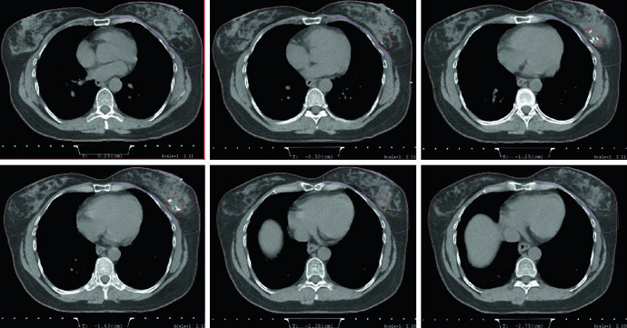
The figures in this chapter do more than illustrate the text. The supine and prone axial images show how the relationship between breast, lung, and heart changes with setup, which is why patient position is treated as a planning decision instead of a matter of habit. The APBI contouring figure turns an abstract expansion rule into a visible anatomic exercise. The boost and APBI plan figures then show how beam choice follows target depth and geometry rather than convention alone.
Read together, the chapter delivers a very consistent message. Early breast radiotherapy should be planned with a standardized technique, careful review of surgery and imaging, reproducible simulation, strict respect for anatomic breast borders, and continuous attention to the heart and lungs. The text does not need embellishment to be persuasive. It works because each recommendation, from 1.5 to 2 mm CT slices in APBI to inclusion of part of the pectoralis muscle at the posterior field edge in the prone plan, is tied to a concrete planning consequence.