
A CT simulator in radiotherapy is where patient positioning becomes geometry you can trust through planning and delivery. This article zooms in on one piece that quietly drives setup quality: the external laser system used for alignment, marking, and isocentre localization.
For the full series context, see our Technical Specifications of Radiotherapy Equipment – Full Guide. If you want the broader framing first, use the overview and the article on radiotherapy equipment packages.
CT simulator external lasers: geometry and clinical use
The document is explicit: the CT simulator combines internal lasers (to locate the centre of the image plane) with an external laser system for patient alignment. In the technical specification, that same system is tied to alignment, marking, and isocentre localization.
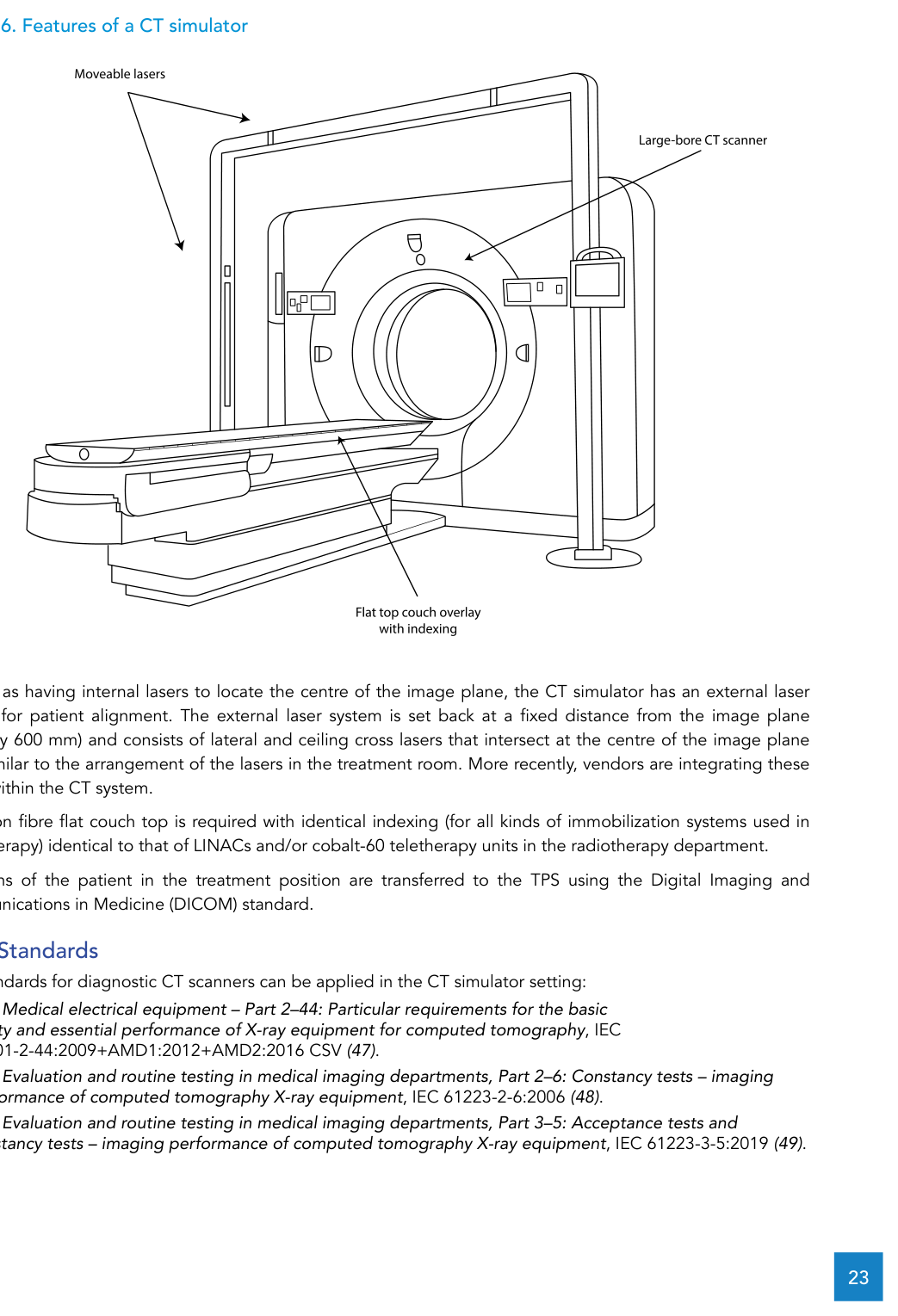
Geometrically, the external laser system is described as being set back from the image plane by a fixed distance (typically 600 mm). It consists of lateral and ceiling cross lasers that intersect at the centre of the image plane axis, mirroring the laser arrangement in the treatment room. The text also notes a recent trend: vendors integrating these lasers into the CT system itself.
As a procurement requirement, the external radiotherapy laser system must include a moveable ceiling laser and moveable lateral lasers, with position control available within the CT simulator room. Laser projection must be at least 50 cm long at the patient plane. Red or green lasers are preferred. The same section ties alignment to the rest of the setup: a flat carbon fibre couch top with indexing identical to the department’s LINAC and/or cobalt-60 teletherapy units, and transfer of CT scans to the TPS using the DICOM standard.
CT simulator: standards and technical specification (alignment-driven)
The document points to diagnostic CT IEC standards as applicable in the CT simulator setting, including IEC 60601-2-44, IEC 61223-2-6 and IEC 61223-3-5. It then lists requirements across imaging, couch mechanics, IT, networking and integration.
Below is a condensed view of the technical specification (keeping the limits and values from the text):
| Subsystem | Requirement | Notes |
|---|---|---|
| CT scanner | Whole body spiral and multi-slice (minimum 16 slices/rotation); gantry aperture ≥ 80 cm; scan FOV ≥ 50 cm; extended FOV ≥ 70 cm | Gantry positioning indicators accuracy ±1 mm or better |
| Couch | Carbon fibre, flat, indexed; horizontal range ≥ 170 cm; max speed ≥ 100 mm/s; position accuracy better than ±0.25 mm; scannable range ≥ 150 cm | Max weight ≥ 180 kg without change in stated performance; couch top sag < 5 mm with an 80 kg patient |
| X-ray generator / tube | High-frequency generator ≥ 60 kW; 80-130 kV; 30-400 mA (step size 5 mA or better); peak anode heat dissipation ≥ 1.1 MJ/min | Dual focal spots |
| Detectors | Solid-state, high performance/low noise; multiple rows with 650+ detectors to acquire at least 16 slices at a time | Text requires freedom from repeated calibrations |
| Console / storage | Networked high-end computer; two ≥ 19" LCD monitors (acquisition + review/processing); disk ≥ 1 TB; store 200,000+ uncompressed 512 × 512 images | Departmental intranet, no internet access; installs/upgrades via CD/DVD; other external device inputs disabled (data protection/virus minimization) |
| DICOM | Fully DICOM compliant | Support: Print (user), Storage (user + provider), Send/Receive, Query/Retrieve (user + provider); provide a DICOM compliance statement |
| Backup / archive | Automatic overnight backup to an external hard drive (all workstations) | External long-term image archive system |
| Dose reporting | Dose display + ability to transfer dose information | DICOM structured dose report available |
| Protocols / software | Typical radiotherapy scan protocols (adult + paediatric) and quality control; automatic mA control (patient size, z-axis, modulation during rotation); metal artefact reduction | Contrast injection pump through IV cannulas or peripherally inserted central catheters |
| TPS/OIS integration | Direct transfer of CT datasets to a virtual simulation workstation, external beam TPS and OIS | Virtual simulation workstation: contouring, isocentre localization, field placement/design (blocks or MLC), DRR generation, and seamless export of admin data/images/volumes/machine parameters to teletherapy equipment, TPS, laser imager and OIS |
| Communication / monitoring | Bi-directional speaker communication | CCTV to view the patient within the gantry bore |
| External lasers | External radiotherapy laser system for alignment/marking/isocentre localization | Moveable ceiling + lateral lasers with room control; projection ≥ 50 cm at patient plane; red or green preferred |
| Printing | Networked dry laser imager |
Source: WHO/IAEA Technical Specifications (CT simulator section)
Performance and safety: acceptance baselines and routine QA
The document ties performance targets and radiation protection to the simulator being safe to operate and stable over time. It also makes it clear that lasers belong in routine QA.
Performance characteristics listed include: slice thickness from sub-millimetre to 8 mm; scan time of 0.6 s or less for full 360° rotation; retrospective reconstruction on raw data with parameter changes (e.g., field of view); and maximum helical scan distance of 1500 mm or more (3 mm slice, pitch 1.5) starting from a cold tube. Modes required: SPR, axial and spiral. For SPR: length > 1500 mm and width ≥ 500 mm; SPR directions AP, PA, left-to-right and right-to-left; protocol reproduction from SPR ±3 mm (or better); distance measurement accuracy in SPR better than twice the pixel dimension. Image quality requirements include reconstruction matrix 512 × 512 or higher; high-contrast spatial resolution at least 15 lp/cm (maximum at 0% MTF); low-contrast detectability 5 mm or less at 0.3% using an adequate phantom on 10 mm slice thickness; CT number accuracy better than 0 ±4 HU for water and -1000 ±10 HU for air.
For radiation safety, the CT simulator must be in a shielded room (lead, concrete or bricks). The control room should be contiguous, with lead glass used to facilitate patient visualization. Shielding thickness can be calculated using Sutton et al. and NCRP Report No. 147 alongside local dose constraints/limits. The simulator room and adjacent areas are treated as controlled areas, and a comprehensive radiation survey is required after installation using a calibrated survey meter.
Facility safety features listed include illuminated X-ray on and X-ray ready signs (at entrances and within the room), ionizing radiation trefoil warning signs at entrances, audio-visual communication between CT simulator room and control room, and emergency-off buttons in both rooms. For QA, the text calls for routine QC of the X-ray system, image quality, laser systems, mechanical features and safety features, and points to IAEA Human Health Series No. 19 (2012) and IEC 61223-2-6, while noting that local standards and regulations may apply.
Immobilization and indexing: what must follow the lasers
Lasers are only useful if the patient can be positioned reproducibly. The document frames immobilization as a requirement for stable, reproducible and comfortable positioning, and links it to couch compatibility and indexing (lock bars as the interface).
EBRT immobilization equipment and accessories
The table reproduces the items and descriptions listed for immobilization (noting the list is for the common supine setup; prone techniques require suitable equipment and should be considered with experienced input and with comfort/reproducibility in mind).
| Region | Item | Description |
|---|---|---|
| Brain | ||
| Brain | Three-point thermoplastic masks | Perforated thermoplastic material suitable for a three-point head base frame |
| Brain | Base frame | Low-density base plate for head, three-point fixation, CT-compatible |
| Brain | Head support | Set of high-density head rests |
| Head and neck | ||
| Head and neck | Five-point thermoplastic masks | Perforated thermoplastic material suitable for a five-point head base frame |
| Head and neck | Base frame | Low-density base plate for head and neck, five-point fixation, CT-compatible |
| Head and neck | Head support | Set of head rests |
| Breast | ||
| Breast | Breast board | Supine support capable of angling up to 25°, including arm and wrist support, CT-compatible |
| Thorax | ||
| Thorax | Wing board | Wing board with hand grips, CT-compatible |
| Pelvis | ||
| Pelvis | Vacuum bags (10 per treatment unit) | Durable plastic skin, 70 cm × 100 cm (polyurethane casts are noted as more durable and can be used instead) |
| Paediatric | ||
| Paediatric | Three-point thermoplastic masks | Perforated thermoplastic material suitable for a three-point head base frame |
| Paediatric | Five-point thermoplastic masks | Perforated thermoplastic material suitable for a five-point head base frame |
| Paediatric | Paediatric headrests | Supine and prone paediatric headrests |
| Paediatric | Vacuum bags | Durable plastic skin, 70 cm × 70 cm (polyurethane casts are noted as more durable and can be used instead) |
| Ancillary equipment | ||
| Ancillary | Knee support | Contoured knee support |
| Ancillary | Feet support | Contoured feet support |
| Ancillary | Water bath* | Water bath for heating thermoplastic material, digital temperature display |
| Ancillary | Compressor | Vacuum bag compressor for inflate and deflate cycles, including connector |
| Ancillary | Radio-opaque skin markers | Radio-opaque point and wire markers for CT and kV planar imaging |
| Ancillary | Locking bars (multiple) | Lock bars compatible with couch indexing and immobilization bases |
| Ancillary | Bolus | 0.3 cm to 2.0 cm thickness (depending on photon/electron energies), skinless, 30 cm × 30 cm |
| Ancillary | Gonad shield | Lead shield, a range of sizes, with holding stand |
| Ancillary | Eye shield | Rounded coated metal shields suitable for orthovoltage or megavoltage electron beams |
*The text notes a hot-air oven as an alternative to a water bath for heating thermoplastic material.
Source: WHO/IAEA Technical Specifications (Table 5)
Conventional simulator and lasers: planar imaging for simulation
When the workflow is built around planar imaging for simulation and isocentre verification, the document describes the conventional simulator as a planning tool for LINAC or cobalt-60 teletherapy treatments, with similar gantry/collimator/couch geometry and an X-ray tube replacing the high-energy source.
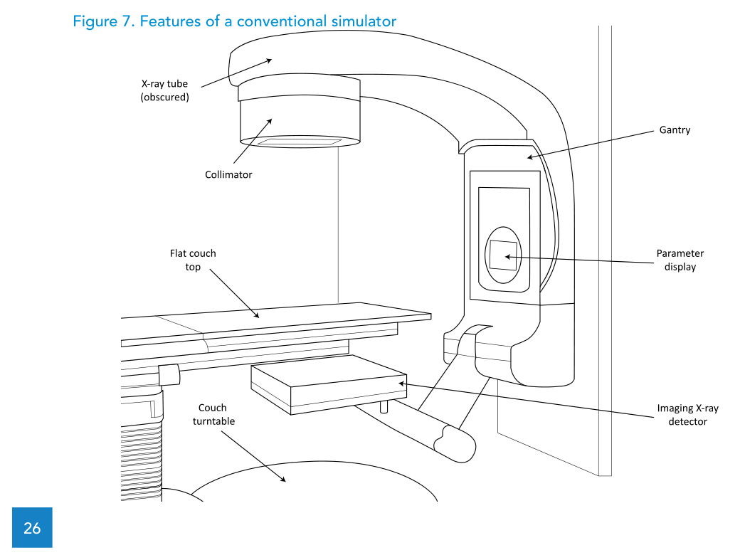
Volumetric imaging (sim-CT cone beam CT) is mentioned as an option, but with inferior image quality compared to diagnostic CT and limited planning applicability; the specification provided does not include this option. Among the technical requirements, the text includes an isocentric motorized gantry with ±180° rotation and a maximum mechanical isocentre sphere diameter of 2.0 mm, and it specifies four mounted external lasers (two lateral cross lasers, one ceiling cross laser and one sagittal line laser) intersecting at the mechanical isocentre.
WHO checklist (Annex 4): key items for a conventional simulator
The WHO/IAEA template adds lifecycle and commissioning elements that are easy to miss in a spec sheet. Here is a short selection, keeping the values and requirements from the annex text.
| Item | Specification |
|---|---|
| Clinical purpose | X-ray imaging of patients for radiotherapy treatment planning |
| Level/setting | Hospital; Radiation Oncology Department |
| Functional overview | Planar imaging unit with gantry/collimator/couch to simulate treatment position; DICOM-compatible for image transfer to a TPS |
| Gantry/isocentre | Motorized isocentric gantry, ±180°; mechanical isocentre sphere diameter ≤ 2.0 mm |
| Focus-to-isocentre distance | Adjustable, at least 80-100 cm |
| Generator | 30 kW high-frequency; up to 125 kVp and 300 mAs (radiography) and 4 mA (fluoroscopy) |
| Field | Collimator rotation ≥ ±90°; max field size up to 40 cm × 40 cm at isocentre (100 cm from focus) |
| Light/radiation coincidence | < 2 mm |
| External lasers | Two lateral cross + one ceiling cross + one sagittal line laser, intersecting at mechanical isocentre |
| Networking | Console includes DICOM 3.0 interface for transfer of digital images to/from a TPS |
| Utilities | Three-phase electrical power and air-conditioning |
| Commissioning | Acceptance testing; commissioning of imaging system; baselines for QC; comprehensive radiation survey |
| Warranty | At least 12 months |
| Maintenance / parts | ~4 service days per year; spare parts availability post-warranty 9 years minimum; onsite spare parts kit recommended |
| Estimated lifespan | 10 years |
Source: WHO/IAEA Technical Specifications (Annex 4)
Mould room: blocks and cut-outs when they are required
The document treats mould room equipment as required for cobalt-60 teletherapy practice (when electron beams are used clinically) and for LINAC practice when an MLC is not included, while also noting that even with an MLC some cases may need a customized block. Block/cut-out shape transfer from the TPS should be supported via DICOM or via printouts at a defined distance to the source (usually at the isocentre plane).
Mould room equipment for EBRT
The table lists the equipment items and key capacity/dimension details; the text adds that PPE (gloves, eyewear, gown) and hand wash are also required.
| Item | Description |
|---|---|
| Fume cupboard | Cabinet with work bench, sink, floor mat and integrated air cleaning system |
| Melting pot (alloy dispenser) | Temperature control up to 120 °C with digital readout; alloy capacity at least 50 kg |
| Stock of LMPA | 70 °C melting point (alloy of bismuth, lead, tin and cadmium) |
| Cooling plate | Aluminium cooling plate, at least 30 cm × 30 cm, levelling adjustment |
| Foam blocks (consumable) | Styrofoam blocks 2 cm thick (electrons) and 7 cm thick (photons) |
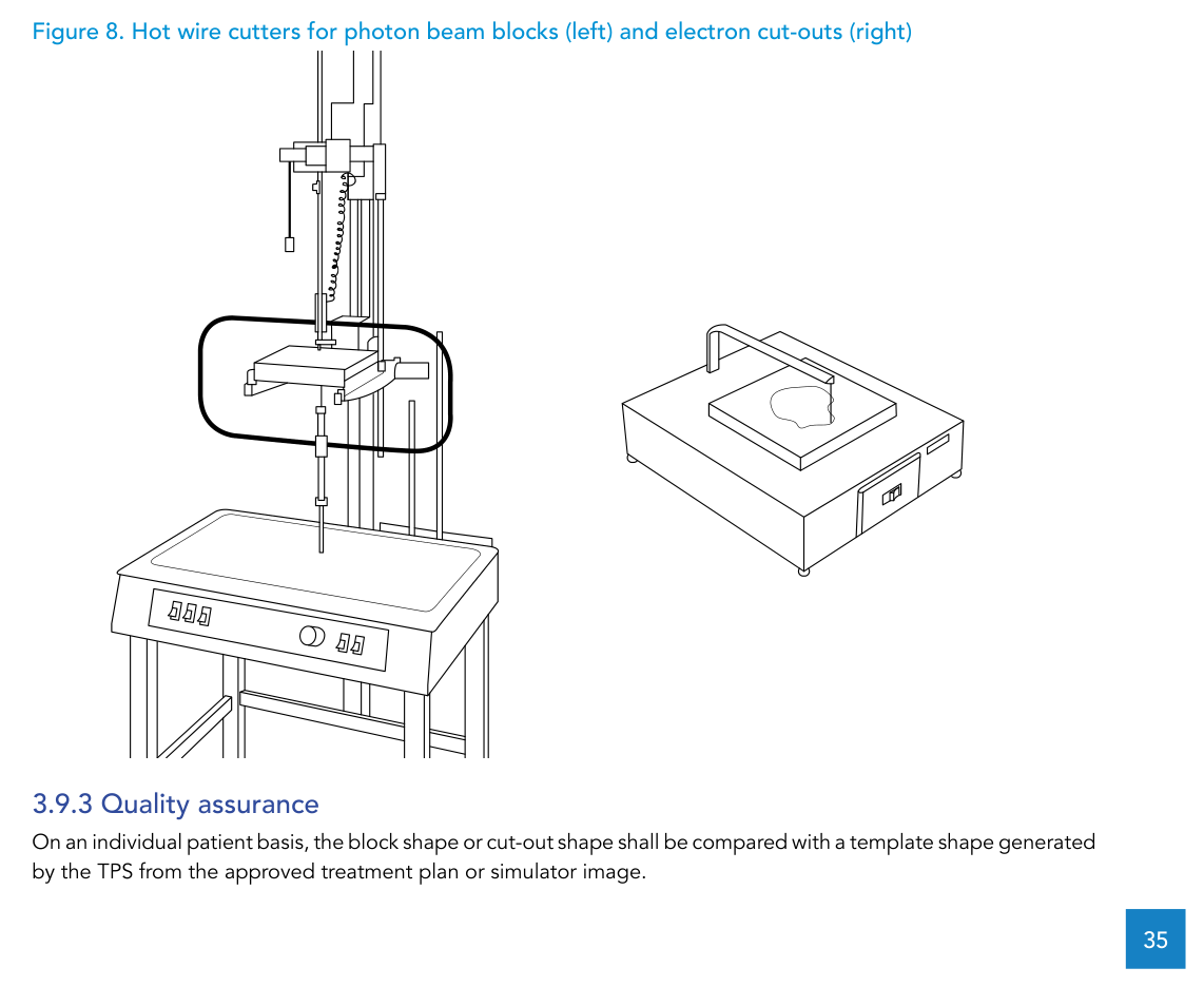
| Hot-wire cutter for electron cut-outs | Perpendicular cutting; heated metal cutting wire; handle foam blocks up to 25 cm × 25 cm; stock of cutting wire |
| Hot-wire cutter for photon beam blocks | Divergent cutting (manual or automated), adjustable height of block arm and source point; handle foam blocks up to 7 cm × 30 cm × 30 cm; stock of cutting wire |
| Tools | Block grip tool, metal file, clamps, alloy pourer |
Source: WHO/IAEA Technical Specifications (Table 6)
For QA, the requirement is patient-specific: the block or cut-out shape is compared with a template generated by the TPS from the approved plan or simulator image.
Dosimetry and QC: end-to-end testing and the EPID trend
The document frames QA as end-to-end: commissioning individual components (simulator, TPS, treatment unit) is not sufficient on its own. It describes an anthropomorphic phantom being taken through simulation, planning and delivery, with measured dose expected to match the planned dose.
It distinguishes reference dosimetry from relative dosimetry, mentions radiochromic film as a useful 2D relative dosimeter, and highlights electronic 2D detector arrays for commissioning dynamic wedges and for commissioning and ongoing QA of IMRT services (with 1D arrays noted as not suitable for IMRT). It also calls out the need to quantify imaging dose from simulation and in-room verification X-ray imaging, and recommends involving a clinically qualified diagnostic radiology physicist when needed for radiology dosimetry equipment and kV image quality phantoms.
Finally, the document notes a trend toward using the EPID for QC (e.g., patient-specific IMRT QA, MLC tests, field size tests). It lists efficiency and replacing consumable radiochromic film as advantages, while requiring careful EPID commissioning as a dosimeter and the availability of licences, calibrations and image access.
For the broader EBRT equipment picture beyond the simulation/support slice covered here, see our dedicated article on EBRT equipment technical specifications.