
This article is a practical slice of radiotherapy equipment technical specifications for external beam radiotherapy (EBRT). Based strictly on the text provided, it summarizes what has to show up in a specification for LINACs and cobalt-60 teletherapy units, plus the room-safety and QA implications the document ties to those systems.
For series context, see the overview article and the post on how radiotherapy equipment packages are defined. For the full map of the topic, use the Technical Specifications of Radiotherapy Equipment – Complete Guide.
Standards: why the specification starts with IEC 60601
The document treats standards as the baseline for basic safety and essential performance in medical electrical equipment, and it uses that baseline to frame what “technical specification” means in radiotherapy.
It highlights IEC 60601-1 as a general standard and notes that it, together with the collateral 60601-1-X family, applies to medical electrical equipment. It also calls out the International Basic Safety Standards as applying to medical equipment that produces ionizing radiation. In this framing, manufacturer compliance with IEC standards is expected to provide equipment safety features, while room and facility requirements are described as complementary protections.
For LINACs, the text cites particular IEC standards (for example IEC 60601-2-1 and IEC 60601-2-68), record/verify safety (IEC 62274), and coordinate conventions (IEC 61217), alongside GSR Part 3.
Radiotherapy equipment technical specifications: LINAC (Package 1 and 2)
The specification is written to cover a single-energy LINAC (Package 1) and a multi-energy LINAC (Package 2), with Package 2-only items explicitly flagged.
Mechanically, it specifies a motorized, isocentric gantry with 100 cm SAD, rotation ±180°, isocentre clearance > 30 cm, and a mechanical isocentre with maximum diameter ≤ 2 mm for collimator, gantry and couch axes. The collimating head has motorized rotation ≥ ±90°, maximum photon field size 40 cm × 40 cm at isocentre (50% isodose level), and minimum field size no more than 4 cm × 4 cm (50% isodose level), with asymmetric jaws that can at least cross the central axis. It also fixes light/radiation coincidence to ≤ 2 mm, an optical distance indicator range of at least SAD ±20 cm, and an optical back pointer.
For beam options, it requires 6 MV photons with a flattening filter and a variable dose rate from 50 MU/min up to at least 400 MU/min. In Package 2, it adds a second photon energy of 10 MV (with a flattening filter) and electron energies of 6, 9, 12 and 15 MeV, with electron dose rate at least 400 MU/min. Package 2 also includes an integrated MLC with at least 80 motorized leaves and maximum 1 cm leaf width at isocentre, interleaf leakage < 4%, and leaf position accuracy ≤ 1 mm at the isocentre plane. For electrons, it specifies applicators up to at least 20 cm × 20 cm, with source-to-end-of-applicator distance 95 cm to allow 5 cm clearance between patient and applicator.
Beam monitoring is described as an independent dual internal ion chamber system for dose, dose rate, symmetry and beam steering, with interlocks. For radiation beams, symmetry shall be ≤ 2% and flatness ≤ 3%. The document defines flatness in the central part of the beam and it can be written as:
$$F = \frac{D_{\max} – D_{\min}}{D_{\max} + D_{\min}}$$
where $D_{\max}$ and $D_{\min}$ are the maximum and minimum doses within the central 80% of the beam width; $F$ is expressed as a percentage and measured in the largest field size at 10 cm depth.
The treatment couch is specified with motorized lateral/longitudinal/vertical motions and isocentric rotation up to ±90°, a carbon fibre indexed tabletop, lateral range at least ±20 cm, longitudinal range > 70 cm, vertical motion from isocentre down to at least 60 cm below, sag < 5 mm with an 80 kg patient, and maximum weight at least 180 kg.
Package 1 vs Package 2: what the text explicitly differentiates
This table keeps only the items the document flags as belonging to Package 2 (or as the Package 1 alternative).
| Item | Package 1 | Package 2 |
|---|---|---|
| Photon energies | 6 MV | 6 MV + 10 MV |
| Electrons | — | 6, 9, 12 and 15 MeV |
| Integrated MLC | — | ≥ 80 leaves; 1 cm max; leakage < 4%; accuracy ≤ 1 mm |
| Portal imaging | Cassette/film or CR | Amorphous silicon EPID (≥ 30×30 cm) with DRR comparison; motorized arm and anti-collision |
The text adds a practical note on EPID: beyond upfront cost, there are additional maintenance costs; the panel may fail during the LINAC lifetime and replacement can be significant if it is not covered by a maintenance contract.
Radiation safety for LINACs: room design, controlled areas and interlocks
In the document, radiation protection is not treated as a construction afterthought. The bunker, access logic and surveys are presented as part of what prevents accidental exposure of staff and the public.
The LINAC is housed in a concrete bunker, and shielding design is linked to references such as IAEA Safety Reports Series No. 47, NCRP Report No. 151 and ISO-16645:2016, together with local dose constraints and dose limits. Because the gantry can rotate 360°, shielding has to be considered in the floor and ceiling as well as walls. Where space permits, a maze reduces scattered radiation at the entrance without requiring door shielding; if space is limited, a maze-less room is possible but requires a heavy shielded motorized door. Under the Basic Safety Standards classification system, the treatment room is designated as a controlled area.
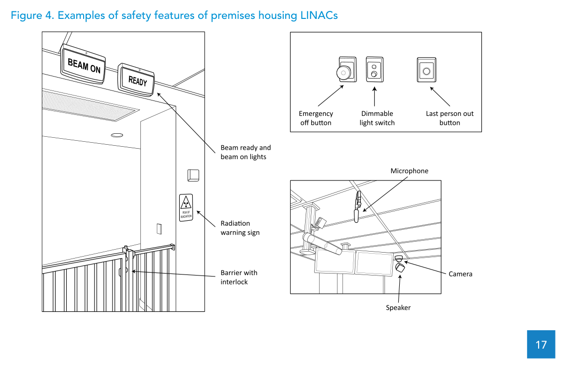
After installation, it calls for a comprehensive radiation survey around the bunker to confirm compliance with local regulations, using calibrated survey meters. It lists premise safety features such as beam-on and beam-ready illuminated signs, the ionizing radiation trefoil warning sign, facility access interlocks, a last-person-out button, audio-visual communication between treatment and control rooms, and emergency-off buttons in both rooms.
Neutrons above 8 MV: calculation, added shielding and activation
For LINAC photon energies above 8 MV, the text highlights the need to consider neutrons generated in the accelerator head and neutron-capture gamma radiation.
Even with concrete sized for primary and scattered radiation, control measures may be needed at the entrance. The text ties this to methodologies used to calculate neutron and capture-gamma dose at the entrance and to size added shielding (lead and a neutron absorber, typically borated polyethylene) to meet the required dose constraint. Maze design (length, number of turns and cross-section) is also described as a way to reduce neutron dose at the entrance. During bunker surveys at commissioning, the recommendation is to use both a neutron meter and an ionizing radiation survey meter to confirm dose level at the entrance.
The text also points to short-term activation products in the accelerator head immediately after high-energy photon irradiation. It identifies aluminium-28 as a dominant short-term activation product in a Varian ClinacTM, with a half-life of 2.24 min, and advises a short delay before staff enter the treatment room. Over the 10–15 year lifecycle, long-term activation of the LINAC head may need to be addressed at decommissioning, with the local radiation regulator consulted.
LINAC quality assurance: dosimetry and geometry as routine
To ensure safety and treatment quality, the document recommends routine quality control testing focused on stable, accurate dosimetry and accurate, reproducible geometry, including optical, mechanical and imaging systems.
Reference dosimetry is tied to a calibrated dosimeter and an absorbed-dose-to-water code of practice (explicitly citing IAEA Technical Reports Series No. 398), alongside international recommendations and any applicable local standards and regulations.
Cobalt-60 teletherapy: simplicity, decay and SAD choices (80 cm vs 100 cm)
The cobalt-60 teletherapy unit is described as mechanically similar to a conventional LINAC (gantry, collimator and couch), but it replaces the electrical generation of megavoltage photons with a high-activity cobalt-60 source.
Against the LINAC photon-generation chain described in the text, it lists cobalt-60 advantages as simpler design and fewer infrastructure services, translating to lower purchase cost and lower running and maintenance costs, which are important considerations for LMICs. It also lists the disadvantages: source decay and additional radiation safety and security considerations for the radioactive source.
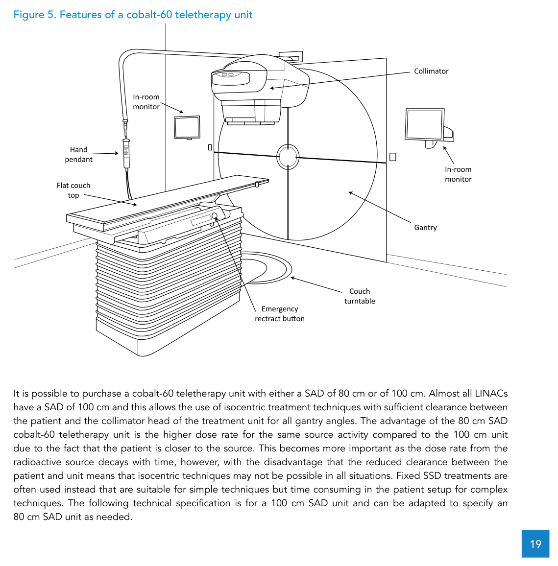
On SAD, the text notes that cobalt-60 units can be purchased with 80 cm or 100 cm. It points out that almost all LINACs have SAD 100 cm, enabling isocentric techniques with sufficient clearance between patient and the collimator head at all gantry angles. The 80 cm SAD option has higher dose rate for the same source activity (patient closer to the source), but reduced clearance can limit isocentric techniques. The technical specification presented is for a 100 cm SAD unit and can be adapted to specify an 80 cm SAD unit as needed.
Because dose rate decreases with time due to decay, the text says the cobalt-60 source has to be replaced at regular intervals, and that lower dose rate leads to longer treatment times and reduced department efficiency. It encourages planning for a new source in the year before the 5-year lifetime is reached. If a department plans two or more units, it recommends selecting both 80 cm and 100 cm SAD units to optimize long-term use of sources, including cascading sources from the 100 cm unit to the 80 cm unit. It also notes that source diameter affects penumbra width and initial dose rate; the specification gives 2.5 cm or less, and it mentions that smaller diameters (for example 1.5 cm or 2.0 cm) can improve penumbra at the expense of initial dose rate.
Cobalt-60 unit (SAD 100 cm): numbers and components that define procurement
For a 100 cm SAD cobalt-60 unit, the text fixes minimum dose-rate performance, isocentric geometry, collimation, couch and console elements, and it points to standards such as IEC 60601-2-11, IEC 61217, ISO-2919 and IEC TR 63183.
| Block | Requirement |
|---|---|
| Source and initial performance | Shielded source ≤ 2.5 cm; initial minimum dose rate ≥ 2.0 Gy/min (10×10 cm; 100 cm SSD; dmax in water); symmetry ≤ 3%; flatness ≤ 3% |
| Geometry | Motorized gantry ±180°; SAD 100 cm; mechanical isocentre ≤ 2 mm (collimator/gantry/couch); clearance ≥ 30 cm with accessories |
| Collimation | Max field 40×40 cm (100 cm SAD), min 1×1 cm; asymmetric collimators capable of shielding half the beam; rotation ≥ ±90°; trimmers to reduce penumbra < 10 mm (if needed) |
| Optical indicators | Light/radiation field coincidence ≤ 2 mm; ODI range ≥ SAD ±20 cm; optical back pointer |
| Wedges | Universal wedge up to 60° or 15°/30°/45°/60° set; interlocks requiring positive confirmation |
| Couch | Motorized vertical/longitudinal/lateral with isocentric rotation ±90°; carbon fibre indexed tabletop; lateral ±20 cm; longitudinal >70 cm; vertical down to ≥60 cm below isocentre; sag <5 mm (80 kg); max weight ≥180 kg |
| Imaging and accessories | Portal imaging solution with portable cassette holder, four MV-optimized cassettes and processing (film or CR); transparent shadow tray for blocks up to 20 kg with console interlock |
| Operation | Hand pendant; in-room monitor; front pointer; CCTV with at least two in-room cameras with pan/zoom; two-way intercom; four mounted lasers (two lateral cross, one ceiling cross, one sagittal line) |
| Power and contingencies | UPS to immediately retract source during power outage; T bar for manual source retraction |
| Console and record/verify | Computerized control console with audio-visual radiation monitor, interlock display and dual-channel timer; removable on/off key; hierarchical modes; interface with OIS for record and verification |
Safety and quality assurance in cobalt-60 teletherapy
For premises, the document again ties radiation protection to a concrete bunker and maze-versus-door design, and it adds security requirements: a security door is needed (either as a standalone security door in a maze layout, or as added security components on the shielded door in a maze-less layout). It lists features such as beam-on signs, the trefoil warning sign, facility access interlocks, a last-person-out button, a permanent area monitor warning if the source is open, audio-visual communication, emergency-retract buttons, and security features to prevent unauthorized removal and sabotage.
For QA, it recommends routine quality control testing with regular absorbed-dose measurements under reference conditions, confirmation of relative dosimetry, and routine testing of cobalt-60 source position relative to the collimator rotation axis to confirm correct open position, alongside testing of optical, mechanical and safety features. Reference dosimetry is again tied to an absorbed-dose-to-water code of practice (IAEA TRS-398), with potential local compliance requirements.
CT simulators: what changes versus diagnostic CT
The text describes the CT simulator as a diagnostic CT scanner plus a flat top couch and external lasers, positioned for radiotherapy simulation and direct transfer of patient datasets to a 3D TPS.
It notes that dedicated radiotherapy CT simulators are available with a larger bore (at least 80 cm) compared with the standard 70 cm bore of diagnostic CT, because treatment positioning may involve patient tilt, arms extended (for example with a breast board), or lateral offsets on the couch. It assumes a dedicated large-bore CT will be purchased for simulation and notes limited value for diagnostic use. If resources do not permit a dedicated CT, it recommends arranging access to a radiology CT scanner plus a flat top couch accessory and an external laser system, with a radiation therapist present and with direct transfer of datasets to the 3D TPS. It calls this option highly recommended for Package 1 centres, where only a small percentage of patients are likely to be prioritized for 3D treatment.
WHO Technical Specifications: Cobalt-60 Teletherapy Unit
Beyond the chapter sections, the document includes a WHO/IAEA template for cobalt-60 teletherapy unit technical specifications. The table below summarizes selected fields, keeping the same numerical requirements described in the annex.
| Category | Item | Specification |
|---|---|---|
| Clinical purpose | Purpose | Delivery of gamma ray beams for external beam radiotherapy (EBRT) |
| Clinical purpose | Level of use | Hospital |
| Clinical purpose | Functional overview | Unit with gantry, collimator and couch; interface with a record and verify system (RVS) |
| Technical requirements | Source and initial dose rate | Shielded source ≤ 2.5 cm; initial minimum dose rate ≥ 2.0 Gy/min (10×10 cm; 100 cm SSD; dmax in water) |
| Technical requirements | Symmetry/flatness | Symmetry ≤ 3%; flatness ≤ 3% |
| Technical requirements | Gantry/isocentre | ±180°; SAD 100 cm; mechanical isocentre ≤ 2 mm; clearance ≥ 30 cm |
| Technical requirements | Collimators | Max field 40×40 cm, min 1×1 cm; asymmetric; rotation ≥ ±90° |
| Technical requirements | Light/radiation coincidence | ≤ 2 mm |
| Technical requirements | Couch | Carbon fibre indexed tabletop; rotation ±90°; lateral ±20 cm; longitudinal >70 cm; vertical down to ≥60 cm below isocentre; sag <5 mm (80 kg); max weight ≥180 kg |
| Imaging & accessories | Portal imaging | Portable cassette holder; four MV-optimized cassettes; processing (film or computed radiography) |
| Utilities | Supplies | Single-phase electrical power; compressed air (as needed); air-conditioning |
| Safety/standards | International standards | IEC 60601-1; GSR Part 3; IEC 60601-2-11; IEC 61217; ISO-2919; IEC TR 63183 |
| Maintenance | Warranty | At least 12 months |
| Maintenance | Estimated lifespan | 10–15 years; cobalt-60 source exchange every 5 years |
| Maintenance | Spare parts post-warranty | 10 years minimum |
Source: WHO/IAEA Technical Specifications of Radiotherapy Equipment for Cancer Treatment (Annex 2)