Radiotherapy equipment technical specifications are not a paperwork exercise. In EBRT, they set the baseline for what you can measure, repeat and justify when you evaluate delivered dose over months and years.
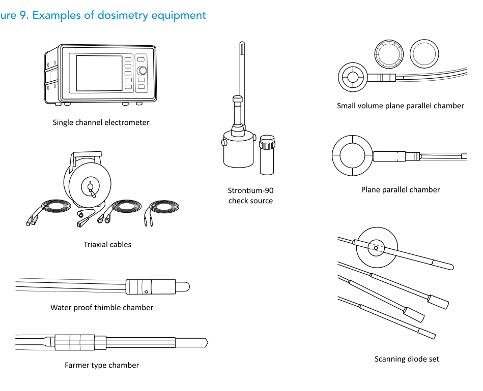
This article summarizes the WHO/IAEA dosimetry and quality control (QC) instrumentation for EBRT (Tables 7 to 11), with examples in Figures 9 to 11. For wider context, see our complete guide and the related article on equipment packages. Standards cited: IEC 60731:2011+AMD1:2016 CSV; IEC 61674:2012.
Radiotherapy equipment technical specifications: reference dosimetry (Table 7)
Answer first: Table 7 defines the reference set that supports traceable measurements, including chambers, electrometers, environmental instruments, check sources and a water phantom aligned with TRS 398.
Two practical messages are hard to miss. First, calibration is treated as scheduled work with an explicit two-year interval at PSDL/SSDL for reference equipment. Second, the table calls out handling-related failures where redundancy (a spare triaxial cable) prevents avoidable downtime.
Reference dosimetry equipment (Table 7)
| Item | Description | Comments |
|---|---|---|
| Farmer-type ionization chamber (1 reference/department and 1 field/unit) | Waterproof Farmer-type chamber for reference dosimetry; graphite wall material; active volume ~0.6 cm3; TNC or BNC connector; includes cobalt-60 build-up. | Calibration at a PSDL or SSDL every 2 years. Calibration in terms of absorbed dose to water, in conjunction with an electrometer. |
| Plane-parallel ionization chamber (1/department; required only for electron beams) | Plane-parallel chamber with volume ~0.4 cm3 for electron-beam reference dosimetry; BNC or TNC connector. | Calibration at PSDL/SSDL every 2 years or, alternatively, cross-calibration against the reference Farmer chamber within the radiotherapy department. |
| Triaxial cables (1 per electrometer + 1 spare) | Triaxial 20 m extension cables with BNC or TNC connector. | A spare cable is recommended because these cables often fail after repeated handling or mishandling. |
| Reference-class electrometer (1/department) | Single-channel electrometer for radiotherapy dosimetry, reference class per IEC 60731; BNC or TNC connector; includes carry case. | Internal desiccator requires replacement at intervals depending on humidity. Calibration at PSDL/SSDL every 2 years. |
| Field-class electrometer (1/treatment unit) | Single-channel electrometer for radiotherapy dosimetry, field class per IEC 60731; BNC or TNC connector. | Same considerations as the reference-class electrometer. |
| Thermometer (1/treatment unit) | Glass thermometer (spirit type), 0°C to 50°C, scale resolution 0.2°C or better; include a calibration certificate. | The use of mercury thermometers should not be allowed. |
| Barometer (1 or 2/department) | Digital or aneroid barometer, 0.01 kPa resolution, calibration certificate; pressure-reading range suitable for the department’s elevation. | Range matters at high elevation. Atmospheric pressure decreases by about 1% per 80 m elevation. |
| Strontium-90 check source for Farmer chamber (1/department) | Strontium-90 check device for a Farmer-type chamber, including the chamber holder. | Including radioactive material requires compliance with requirements from the local radiation regulator. |
| Strontium-90 check source for plane-parallel chamber (1/department) | Strontium-90 check device for a plane-parallel chamber, including the chamber holder. | Same regulatory requirements associated with radioactive material. |
| Constancy meter (1/treatment unit) | Automated system for daily measurements of LINAC beams or a cobalt-60 teletherapy beam. Requires multiple detectors (at least 5) for beam symmetry and beam output. Must include software for control and calibration, plus long-term display and storage. The system should allow tolerance limits to be set and should notify when readings are out of tolerance. | |
| Water phantom (1/department) | Water phantom for reference-dose measurements according to IAEA Technical Reports Series No. 398. Measurement depth adjustable manually or via a motorized system to at least 20 cm, with 0.1 mm steps (or finer). Include holders for a Farmer chamber and a plane-parallel chamber. |
Source: WHO/IAEA Technical Specifications (Table 7)
Table 8: relative dosimetry and commissioning
Answer first: Table 8 specifies the equipment used to characterize beams for commissioning, centered on a 3D water scanning tank system and complemented by diodes, film tools and detector arrays.
The table goes into the details that drive day-to-day reliability: scan volume limits, positioning accuracy and reproducibility, bias range, minimum current resolution and leakage current limits, plus explicit requirements on software capabilities and data export to a commercial TPS.
Relative dosimetry equipment (Table 8)
| Item | Description | Comments |
|---|---|---|
| 3D scanning water tank system (LINAC commissioning) |
3D scanning tank system for commissioning (tank + lift table + reservoir + dual electrometer/control + Windows laptop + software); includes 2 waterproof thimble chambers (~0.13 cm3) and cables. Scan volume up to 480 x 480 x 400 mm3; detector position accuracy ±0.1 mm; reproducibility ±0.1 mm; motorized X/Y/Z scanning (ion chambers or diodes). Lift table: 500 mm vertical travel; ±5° rotation in the XY plane. Dual electrometer/control: 50–400 V bias; 10 fA minimum resolution; leakage current < 250 fA; controls movement and interfaces with the electrometer. Reservoir: bi-directional transport; capacity > 200 L. Software: scan optimization, data handling/analysis and TPS transfer; desirable text export of profiles/PDD (Notepad/Excel); modules should support transfer to a commercial TPS. Accessories: holders for Farmer/thimble/plane-parallel/diode detectors; cables between computer/controller/tank; 2 triaxial TNC/BNC cables + 1 equivalent spare. |
The specification should state which commercial TPS the beam data will be exported to. The laptop for the control software may be purchased locally and separately. |
| Plane-parallel ionization chamber | Small-volume plane-parallel chamber (~0.05 cm3) for electron-beam relative dosimetry; BNC or TNC connector. | |
| Scanning diode set | Waterproof shielded diode, unshielded diode and reference diode; active diameter ≤ 2 mm. | |
| Radiochromic film | Self-developing radiochromic film, sensitivity up to 10 Gy, for radiotherapy dosimetry applications. | Consumable. |
| Film scanner | Flatbed transmission scanner (A4 or A3) with separate red, green and blue channels. | |
| Film analysis software | Software for radiochromic film dosimetry, including calibration, image display and comparison of film dose planes with TPS-generated dose planes; include at least one perpetual license. | |
| Build-up caps | PMMA or brass build-up caps for a Farmer-type chamber and a thimble chamber, suitable for photon energies 6 MV and 10 MV (15 or 18 MV). | |
| ESTRO mini-phantom | ESTRO mini-phantom per ESTRO Booklet No. 3 (77) for in-air measurements, with a cavity for a Farmer-type chamber mounted parallel to the beam axis; required only if using the ESTRO Booklet No. 3 formalism for independent MU checks. | |
| Solid water block set | Water-equivalent plates: at least 1 plate of 0.1 cm, 2 plates of 0.2 cm, 1 plate of 0.5 cm and 29 plates of 10 mm. Outer dimensions 30 cm x 30 cm. Include adapter plates for a Farmer chamber, a 0.13 cm3 thimble chamber, a 0.4 cm3 plane-parallel chamber and a 0.05 cm3 plane-parallel chamber. | |
| Two-dimensional detector array (dynamic wedge or IMRT) |
2D array with > 700 detectors; centre-to-centre spacing ≤ 1 cm; covers at least 20 cm x 20 cm; include an appropriate phantom. Software should control data collection, import dose planes from a commercial TPS and provide tools to compare measured and TPS dose planes. Include a universal gantry mount to attach the array to the LINAC head. |
1D arrays are also available and can be used to commission dynamic wedges, but they are not suitable for the IMRT application. |
Source: WHO/IAEA Technical Specifications (Table 8)
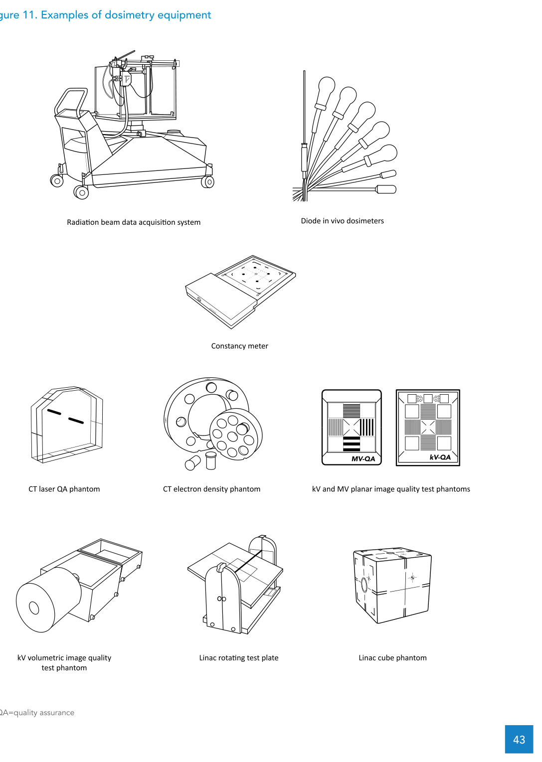
Table 9: quality control equipment
Answer first: Table 9 lists tools and phantoms for geometric checks, alignment and image quality testing, spanning a digital level through EPID, kV planar imaging and kV volumetric imaging.
The mix is intentional. Simple items (graph paper and rulers) sit alongside phantoms and software because practical QC combines quick repeatable checks with more structured measurements.
Quality control equipment (Table 9)
| Item | Description | Comments |
|---|---|---|
| Digital level | Digital level with 0.1° display resolution. | |
| LINAC alignment phantom | Cube phantom or rotating test plate used to check LINAC cross-hairs, lasers and light field size at gantry angles 0°, 90° and 270°. | |
| Laser alignment phantom (CT simulator) | PMMA phantom with 2 mm wide notches for alignment to lateral, ceiling and sagittal lasers. | |
| Electron density calibration phantom | Phantom for CT number to electron density calibration for radiotherapy planning: includes plugs spanning electron densities from lung to bone; body made of water-equivalent material; electron densities of plugs and body provided in the user manual. | |
| EPID image quality phantom | Phantom and software for EPID image quality tests, including high-contrast and low-contrast resolution. | |
| Image quality phantom for kV planar imaging | Phantom for general radiography X-ray image quality tests: low-contrast resolution, high-contrast detectability, line pair resolution and sensitometric analysis. | |
| Image quality phantom for kV volumetric imaging | Volumetric phantom for CT image quality tests: CT number, uniformity, noise, slice thickness, high-contrast resolution and low-contrast resolution. | |
| Graph paper | A3 and A4 graph paper with 1 mm grid. | |
| Metal rulers (1 m and 30 cm) | Metal rulers of 1 m and 30 cm with at least 1 mm resolution. |
Source: WHO/IAEA Technical Specifications (Table 9)
Table 10: in vivo dosimetry (diode system)
Answer first: Table 10 specifies a diode-based in vivo dosimetry system, including entrance detectors for photons and electrons, a surface detector, an out-of-field detector and a multi-channel controller/electrometer.
The text notes competing in vivo technologies (MOSFET, diode, TLD, RPLD, OSLD and film). It uses the diode system as the worked specification and highlights two practical advantages: instantaneous readout and reusability.
In vivo dosimetry equipment (Table 10)
| Item | Description | Comments |
|---|---|---|
| Photon entrance dose detector | Diode detectors with a flat surface and sufficient build-up for photon energies from 6 MV to 15 MV. | Temperature, dose-rate and energy dependence should be accounted for during calibration and clinical use. |
| Electron entrance dose detectors | Diode detectors with a flat surface and sufficient build-up for electron energies from 6 MeV to 18 MeV. | |
| Surface entrance detector | Diode detector with a flat surface and minimal build-up. | |
| Out-of-field detector | Diode detector with 5 mm surrounding build-up for out-of-field dosimetry. | |
| Controller and electrometer | Multi-channel controller and electrometer enabling calibration and reading of diode signals. |
Source: WHO/IAEA Technical Specifications (Table 10)
Table 11: radiology dosimetry (kV and CT)
Answer first: Table 11 consolidates instrumentation for radiology dosimetry, spanning kV beam calibration, kVp measurement, aluminum filter sets, plus a dedicated CT dosimetry kit (pencil chamber and CTDI phantom).
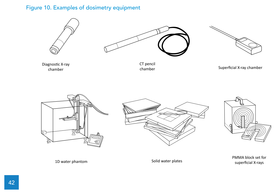
The figure labels include “Diagnostic X-ray chamber”, “Superficial X-ray chamber” and a PMMA block set for superficial X-rays. That matches the table’s emphasis on kV instrumentation that supports calibration and consistent measurement in radiology and CT.
Radiology dosimetry equipment (Table 11)
| Item | Description | Comments |
|---|---|---|
| Ionization chamber | Active volume ~6 cm3; calibrated for X-ray beams; energy dependence < ±2% in the kV energy range. | |
| kVp meter | Solid-state kVp meter for radiography from 50 to 150 kVp; 0.1 kVp resolution. | |
| Controller | Combined electrometer and display capable of showing dose, dose rate, exposure time (ms) and, separately, kVp (with the kVp meter). | |
| Aluminum filter set | High-purity (99%) aluminum filters, 100 mm x 100 mm; total thickness at least 7.5 mm; minimum thickness 0.05 mm. | |
| Pencil ionization chamber (CT dosimetry) | 10 cm active length; calibrated for X-ray beams; energy dependence < ±3% in the kV energy range. | |
| CT phantom | Nested PMMA phantom for CTDI measurements: 32 cm diameter, 15 cm length; central and peripheral inserts for the pencil chamber. |
Source: WHO/IAEA Technical Specifications (Table 11)
Radiation safety and protection for check sources (3.10.4)
Answer first: within the dosimetry set, the document highlights one radiation-emitting device: the strontium-90 check source, with clear requirements on who uses it, how it is stored and which regulations apply.
The text describes a low-activity beta source permanently housed in a lead container. It restricts use to clinically qualified medical physicists, requires secure storage in its container and states that local standards and regulations for transport, use and storage of radioactive material must be followed.
Quality assurance and recalibration intervals (3.10.5)
Answer first: stable dosimetry performance underpins radiotherapy quality, and the document sets a clear expectation that reference dosimetry equipment is recalibrated every 2 years at an SSDL or PSDL.
It points to international recommendations for quality control tests and also cites national professional society guidance. Examples named in the text include:
- IAEA, Setting up a radiotherapy programme: Clinical, medical physics, radiation protection and safety aspects, 2008 (Appendix XIII, Table 25).
- IAEA, Development of procedures for in vivo dosimetry in radiotherapy, Human Health Reports No. 8, 2013.
- AAPM, Comprehensive QA for radiation oncology (Task Group 40), 1994.
- AAPM, Diode in vivo dosimetry for patients receiving external beam radiation therapy (Task Group 62), 2005.
- Canadian Partnership for Quality Radiotherapy, Technical quality control guidelines for major dosimetry equipment, 2015.
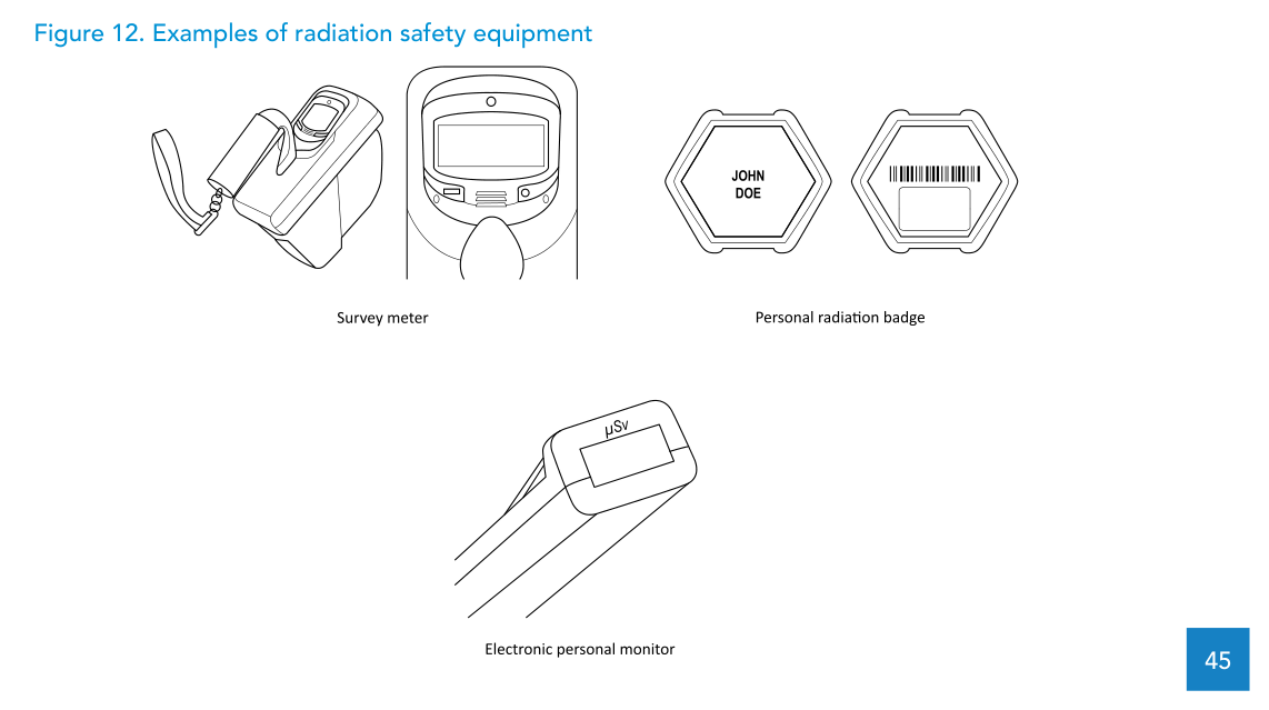
Radiation safety equipment specifications (Table 12 and Figure 12)
Answer first: for EBRT facilities, the document describes safety instrumentation covering survey measurements, neutron measurements when applicable, passive occupational monitoring and direct-read electronic personal monitors.
Radiation protection instrumentation standards referenced: IEC 62387:2020; IEC 60325:2002; IEC 61005:2014; IEC 61017:2016.
Radiation safety equipment (Table 12)
| Item | Description | Comments |
|---|---|---|
| Survey meter | Portable ionization chamber-based survey meter for X-ray and gamma above 25 keV; integrated display; dose-rate & integrated dose modes; 0.5 µSv/hr–50 mSv/hr; energy dependence < 20% (50 keV–1 MeV); include calibration certificate. | Protection-level calibration with caesium-137 required every 2 years. |
| Neutron meter (if photon energies ≥ 10 MV in clinical use) | Spherical rem-counter probe for neutron ambient dose equivalent rate (Sv/hr) per ICRP Publication 60; 30 nSv/hr–80 mSv/hr; energy dependence ~±30% (50 keV–10 MeV); sensitivity < 3 counts/nSv; calibration traceable to primary standards. | Given expense, infrequent use and calibration-access difficulty, departments are encouraged to borrow or share a neutron survey meter rather than purchase their own. |
| Personal radiation monitoring service | Service using passive badges sensitive to X-ray, gamma and beta; exchange every 3 months; provide dose reports promptly after each wearing period; identify readings above national dose limits. | Dose reports may need to be forwarded to the regulator. Regulatory monitoring periods are typically 1 to 3 months. |
| Electronic personal dosimeter | Direct-read personal monitor with audible dose-rate indication; energy 45 keV–1.2 MeV; displays accumulated dose (Sv); includes reset. |
Source: WHO/IAEA Technical Specifications (Table 12)
For the broader context, return to the complete guide.