Target volume delineation and field setup in prostate adenocarcinoma only looks straightforward until the chapter lays out the real workflow. IMRT is presented as the standard external beam technique for both definitive treatment and the postoperative setting, whether that postoperative course is adjuvant or salvage. The message is consistent from the opening paragraph onward: no fractionation schedule performs as intended unless the target is drawn accurately and treatment delivery is image-guided. For the broader series context, see our complete guide to target volume delineation and field setup.
This chapter is not built around one preferred dose schedule. It is built around process. After pathology confirms the diagnosis, the authors move through workup, mpMRI, simulation, image fusion, slice-by-slice CTV definition, and 3D quality review. That sequence is what keeps the discussion coherent across intact-prostate treatment, post-prostatectomy treatment, and elective pelvic nodal coverage. The anatomy changes. The demand for geometric discipline does not.
In This Article
- Initial workup and treatment selection
- Simulation, preparation, and image fusion
- Target volume delineation for the intact prostate
- Table 25.1: dose schedules, margins, and contouring concepts
- Post-prostatectomy target definition
- Elective pelvic nodes and nodal boost strategy
- IGRT, margins, and quality control
- Further reading cited by the chapter
Initial workup and treatment selection
The initial workup starts after pathologic confirmation. The chapter specifically lists digital rectal examination, urinary and erectile function scores, and relevant laboratory studies, including PSA and any additional testing needed when androgen deprivation therapy is planned. mpMRI is recommended for all patients unless contraindicated. The reason is practical rather than generic. mpMRI is used to detect potentially undersampled high-grade disease, define prostate volume, map the size and location of the dominant lesion, evaluate extra-prostatic extension and seminal vesicle invasion, and identify gross postoperative disease that may justify dose escalation.
Treatment selection is deliberately individualized. The authors tie the decision between definitive regimens and postoperative management to NCCN risk group, MRI findings, age, comorbidities, urinary function, and patient preference. That framing matters. The chapter is not asking the reader to start with a dose and fit the patient into it. It starts with anatomy and clinical context, then lets the regimen follow from those findings.
Simulation, preparation, and image fusion
Simulation receives unusual detail because it carries much of the chapter’s logic. At MSKCC, MR-only simulation and planning are preferred for all definitive treatments and for postoperative gross local recurrences. When that is not the pathway, a 2 mm CT simulation is fused with a 3 T MRI acquired in the treatment position. This is more than a convenience. It is the mechanism that links planning geometry to the anatomic boundaries that define the prostate CTV.
For definitive treatment, three fiducial markers are placed at the base, mid-gland, and apex, with or without a rectal spacer provided there is no posterior EPE, and they are inserted at least 5 days before simulation. If dose escalation is planned for a suspected postoperative gross local recurrence, fiducials may be placed at the time of biopsy. Rectal preparation is standardized: a low-fat, low-residue diet, fiber supplement, and simethicone begin 1 week before simulation and continue throughout treatment, with an enema 3 hours before simulation and before treatment when needed. Bladder preparation is equally direct: 16 oz of water 45 minutes before simulation and treatment.
Urethral sparing is handled explicitly. A Foley catheter is used for SBRT simulations and when EBRT is combined with a brachytherapy boost, while MRI-based urethral delineation is offered as an alternative. The patient is positioned supine with leg and pelvic immobilization. SBRT setups must be validated and may use framed or frameless systems. At MSKCC, a thermoplastic mold extends from the mid-abdomen to the mid-thigh and conforms to the inner leg, with a knee cushion added for stability. Simulation borders run from L2 to the mid-femur. The isocenter sits at the prostate or prostate bed, or at the top of the femoral heads when lymph nodes are included.
MRI-to-CT fusion is refined by matching the bladder-prostate interface, the bony anatomy, and the fiducials. The chapter points out that pitch differences between MRI and CT often distort the very interface the planner is trying to trust. Specific MRI sequences such as T1 SPGR or 3D BFFE are therefore relevant to the registration process. If your interest extends to combined external beam and implant workflows, this section connects naturally with our article on image-guided brachytherapy planning, because urethral definition and geometric reproducibility start here, not on treatment day.
Target volume delineation for the intact prostate
For the intact prostate, the chapter organizes the target around CTVpros. The core structure is the entire prostate with or without seminal vesicles depending on the clinical setting. Diagnostic mpMRI is revisited because it helps ensure that gross posterior EPE is not left outside the target. Among imaging sequences, axial T2 MRI is described as the most useful for tumor and EPE. That is a strong statement, and the rest of the contouring guidance clearly depends on it.
The authors advise starting around the mid-gland where the posterior capsule and seminal vesicles are best visualized, then proceeding caudally to the apex. The lateral boundary remains within the levator ani. The anterior boundary follows the anterior fibromuscular stroma. The posterior boundary tracks the rectal interface. Inferiorly, the apex is identified relative to the hourglass shape of the genitourinary diaphragm on the CT slice above. Superiorly, coverage may include the proximal 5-10 mm of the seminal vesicles or the entire seminal vesicles depending on indication. The chapter avoids shortcut geometry. Each slice has to earn its contour from visible anatomy.
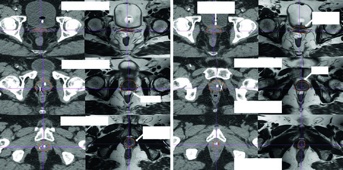
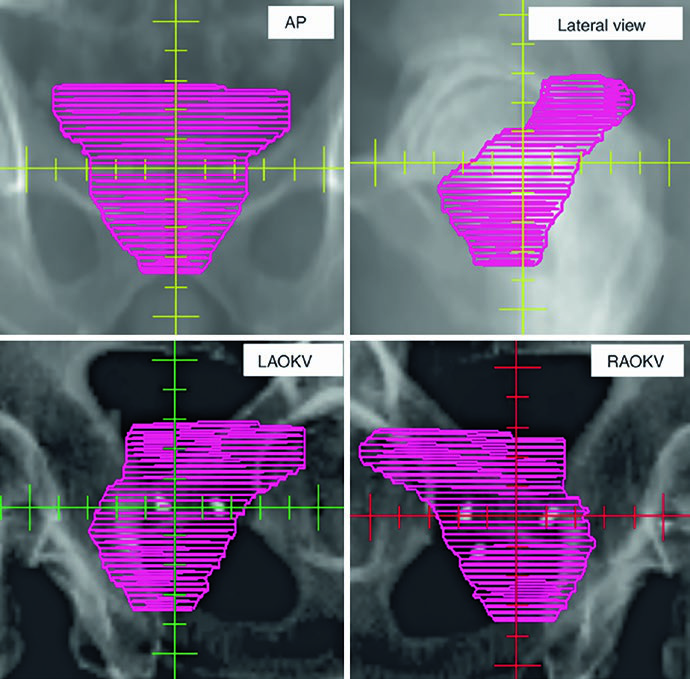
The figures explain why 3D review is treated as a contouring tool rather than a cosmetic step. Figure 25.1 shows a definitive prostate CTV on 2 mm CT fused with T2 MRI, beginning at the seminal vesicles and moving toward the apex. The caption notes that the hydrogel rectal spacer is best seen on T2 MRI and references Atluri et al. on the addition of iodinated contrast to support MRI-independent spacer delineation. Figure 25.2 then projects the CTV in AP, lateral, and oblique views. The gland appears as a globular structure beneath a winged superior component representing the seminal vesicles. If the contour extends too far into the genitourinary diaphragm, that mistake becomes obvious on the 3D projection.
The same projection also exposes irregular contouring from slice to slice. The chapter warns that gross distortions in the reconstructed shape may reflect overcorrection that is not anatomically faithful, especially when the planner is averaging deformation and organ motion across treatment. That is a concise but important observation. In prostate work, many failures are not caused by one dramatic mistake. They arise from repeated small departures from anatomy.
Table 25.1: dose schedules, margins, and contouring concepts
The table below condenses the chapter’s technical framework. It shows what changes across intact-prostate treatment, postoperative treatment, and pelvic nodal irradiation, while making clear that the dose schedules listed are the current MSKCC patterns described by the authors.
| Setting | Protocol | Fraction dose | MSKCC regimen | PTV margin | CTV description |
|---|---|---|---|---|---|
| Definitive | Conventional | 180-200 cGy | 81-86.4 Gy in 45-48 fractions | 6 mm except 5 mm posteriorly | CTVpros: entire prostate with or without seminal vesicles, depending on the scenario and the risk of invasion. Diagnostic mpMRI is used to ensure that gross posterior EPE is not missed. Axial T2 MRI is the most useful sequence for tumor and EPE. Contouring starts around the mid-gland where the posterior capsule and seminal vesicles are best seen. The lateral boundary stays within the levator ani, the anterior boundary follows the anterior fibromuscular stroma, the posterior boundary follows the rectal interface, the inferior boundary is set at the apex relative to the hourglass configuration of the genitourinary diaphragm, and the superior boundary covers the proximal seminal vesicles or the entire seminal vesicles when indicated. Sagittal, coronal, and 3D review are part of quality control. |
| Definitive | Moderately hypofractionated | 240-300 cGy | 70.2 Gy in 26 fractions; 55 Gy in 20 fractions in the low-volume M1 setting; if pelvic nodes are treated, use the nodal regimen below | 5 mm except 3 mm posteriorly | Same intact-prostate CTV concept described above. |
| Definitive | Ultra-hypofractionated (SBRT/SABR) | >500 cGy | 40 Gy in 5 fractions delivered every other day | 5 mm except 3 mm posteriorly | Same anatomic concept for the intact prostate, with extra emphasis on urethral visualization, setup validation, and 3D review. |
| Postoperative | Conventional | 180 cGy with or without a boost for gross disease | 72 Gy in 40 fractions with or without a boost to 78 Gy | 6 mm except 5 mm posteriorly | Prostate fossa CTV within RTOG guidelines. The inferior boundary is about 10 mm below the vesicourethral anastomosis on the last slice with urine. The CTV should not extend into the penile bulb. The anterior boundary follows the pubic symphysis, then gradually tapers off the bladder over roughly 4 slices above the symphysis. The posterior boundary follows the anterior rectal wall or mesorectal fascia. The lateral boundary is the levator ani and obturator internus. The superior boundary extends about 1-2 cm above the pubic symphysis to include seminal vesicle remnants without needing to encompass every hemostatic clip. Sagittal, coronal, and 3D review remain essential. |
| Elective pelvic nodes | Conventional with or without SIB | 180 cGy with or without SIB for gross disease | 45 Gy in 25 fractions with or without SIB to 56.25 Gy in the definitive setting; 46.8 Gy in 26 fractions with or without SIB to 57.2 Gy postoperatively | 8 mm on the elective pelvis; 5 mm on nodal GTV | Modified RTOG approach. Target regions include common, external, and internal iliac chains, obturator nodes, and presacral nodes. No bowel or muscle should be included in the CTV. Contouring starts at the aortic bifurcation. The external iliacs stop at the top of the femoral heads. The internal iliacs and obturators extend to the superior aspect of the pubic symphysis. Presacral coverage extends from the top of S1 to the inferior border of S2. When gross nodal disease is boosted, the diagnostic study that best shows the GTV, such as MRI or PET, should be fused. |
Source: Target Volume Delineation and Field Setup, 2nd Edition (Table 25.1)
a. The dose schedules listed in the chapter are specific to current MSKCC practice. The authors state that prescriptions should be grounded in doses validated for efficacy and safety with the treatment technique being used and with each institution’s own planning and setup allowances.
b. MSKCC PTV margins are tied to its image-guided IMRT workflow. Daily pretreatment kV images are matched to fiducials in the definitive setting and to bone postoperatively. CBCT is performed at least weekly for soft-tissue evaluation, and it becomes daily in hypofractionated schedules together with intrafraction motion management to monitor or correct prostate position.
Post-prostatectomy target definition
After prostatectomy, the anatomy changes and the target logic changes with it. Instead of contouring a gland, the chapter turns to the prostate fossa within RTOG guidelines, using a conventional example of 72 Gy in 40 fractions with or without a boost to 78 Gy for gross disease. The job is no longer to outline an organ. It is to cover the spaces at risk for microscopic residual disease without letting every postoperative landmark expand the target indiscriminately.
The inferior boundary lies about 10 mm below the vesicourethral anastomosis on the last slice containing urine. The text is explicit about not extending the CTV into the penile bulb. Anteriorly, the contour follows the pubic symphysis and then gradually tapers off the bladder over roughly four slices above the symphysis. Posteriorly, the reference is the anterior rectal wall or mesorectal fascia. Laterally, the relevant structures are the levator ani and obturator internus. Superiorly, the volume may extend about 1-2 cm above the pubic symphysis to include seminal vesicle remnants, but it does not need to encompass every hemostatic clip. That last point is especially useful because it stops the planner from converting every surgical marker into a target.
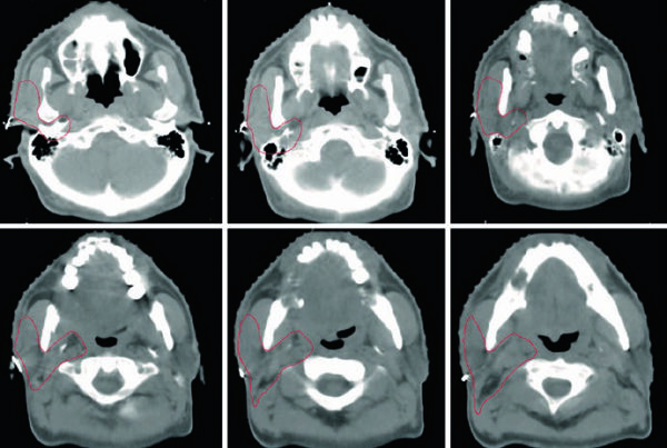
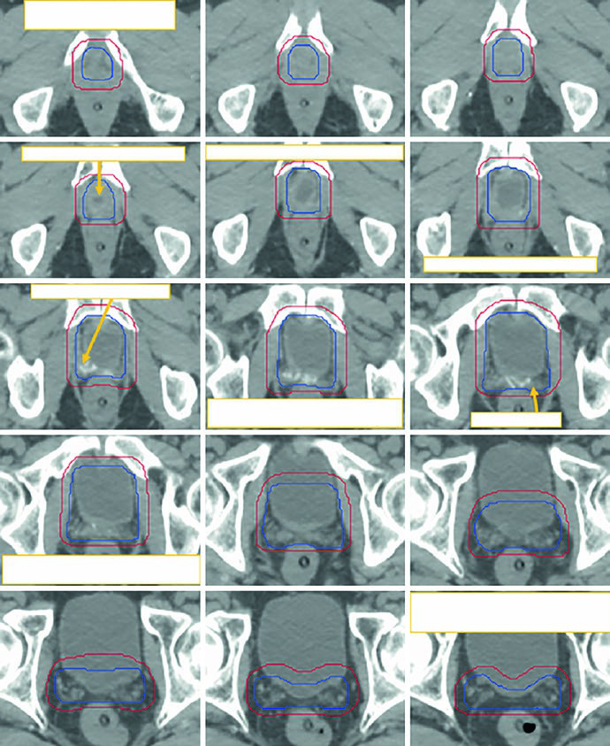
Figure 25.3 demonstrates this with a sequence that runs caudal to cranial on a 2 mm simulation CT acquired with a full bladder protocol. The figure shows the initial CTV in blue and the manually modified PTV in red. The reason for the manual edit is practical: after automatic expansion, the cranial anterolateral rectal region can create an overhanging dumbbell configuration that would overdose the rectum if left uncorrected. The chapter does not dismiss expansion margins. It shows exactly where they need human review.
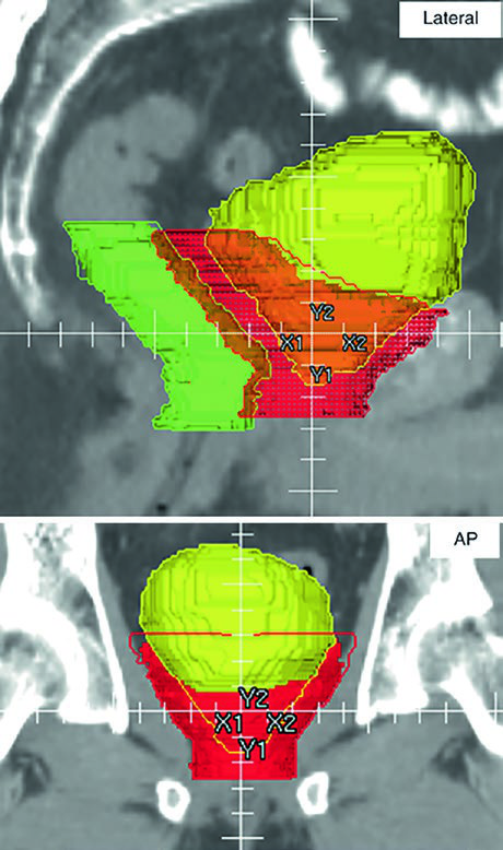
Figure 25.4 extends the point with orthogonal 3D PTV projections. In a postoperative plan, the contours necessarily approach bladder and rectum because potential microscopic disease may involve the anterior perirectal space, the vesicourethral anastomosis, and the new spaces created between the posterior bladder interface, the pelvic floor, and the VUA. The caption highlights overlap with rectum in green and bladder in yellow. Smooth tapering of the anterior PTV boundary above the pubic symphysis is checked on the 3D view because abrupt transitions become vulnerable to day-to-day bladder filling changes despite a full-bladder protocol.
Elective pelvic nodes and nodal boost strategy
When pelvic nodal treatment is added, the chapter uses a modified RTOG approach. The target regions are the common, external, and internal iliac chains, the obturator nodes, and the presacral compartment. One operational rule is stated very clearly: no bowel and no muscle should be included in the CTV. Contouring starts at the aortic bifurcation. The external iliacs end at the top of the femoral heads. The internal iliacs and obturators extend to the superior aspect of the pubic symphysis. Presacral coverage extends from the top of S1 to the inferior border of S2. If gross nodal disease is being boosted, the diagnostic study that best shows the GTV, such as MRI or PET, should be fused.
The regimens listed in the chapter use 45 Gy in 25 fractions with or without SIB to 56.25 Gy for definitive elective pelvic treatment, or 46.8 Gy in 26 fractions with or without SIB to 57.2 Gy in the postoperative setting. Margins also change. The elective pelvis uses 8 mm, while nodal GTV uses 5 mm. That difference matters because pelvic nodal coverage is not just a larger prostate plan. It is a different geometric problem with different anatomic edges.
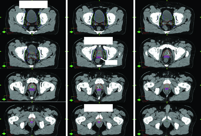
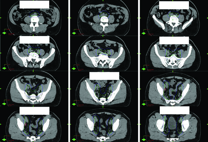
Figure 25.5 provides a detailed example. The patient had regional nodal disease, staged T1cN1M0, Gleason 4 + 4, PSA 22, and was treated with moderately hypofractionated IG-IMRT together with 2 years of Lupron and Abiraterone. The dose-painting course delivered 4680 cGy to the elective pelvis, 5720 cGy to a gross right pelvic node, and 7020 cGy to the prostate and seminal vesicles in 26 fractions. The caption also notes that a 3 T MRI in the treatment position was fused to help define both CTVpros and the rectal spacer. That combination of anatomic and strategic image use is exactly what makes the example valuable.
IGRT, margins, and quality control
One of the most useful points in the chapter appears in the notes below the table. CTVs should be drawn on every slice of the planning CT or MRI, while PTVs depend on fractionation, image guidance, and institutional standards. That sounds obvious, but it has an important consequence: a margin value cannot be separated from the workflow that supports it. Copying the number without copying the imaging discipline behind it strips the recommendation of its meaning.
At MSKCC, the displayed margins are tied to an image-guided IMRT process. Daily pretreatment kV images are matched to fiducials in definitive cases and to bone in postoperative cases. CBCT is performed at least weekly for soft-tissue review. With hypofractionated schedules, kV imaging and CBCT become daily, and intrafraction motion management is used to monitor or correct prostate position during delivery. That is why smaller margins are acceptable in some settings. They are not an act of optimism. They are supported by tighter surveillance.
The chapter also states plainly that the dose schedules listed are specific to current MSKCC practice. Prescriptions should be based on doses validated for efficacy and safety with the technique being used and with each institution’s planning and setup allowances. That footnote is easy to skip and too important to skip. It is the line that prevents institutional practice from being mistaken for an interchangeable universal template.
Further reading cited by the chapter
The further reading list is brief and well targeted. Atluri et al. are cited for the addition of iodinated contrast to a rectal hydrogel spacer so that target delineation and planning can proceed more easily without MRI. McLaughlin et al. are cited for the radiographic and anatomic basis of prostate contouring errors, especially through MRI-to-CT comparisons. If the practical doubt is about the apex, the capsule, or the rectal interface, that is exactly the literature the chapter points back to.
For postoperative contouring, Pollack and the RTOG 0534 SPPORT protocol are highlighted for the prostate fossa and pelvic nodes. Poortmans and the EORTC group are cited for postoperative target definition, even though the authors of this chapter state that their own practice aligns more closely with RTOG guidance. Tyagi et al. support the MR-only simulation workflow in prostate radiotherapy. Zakian et al. are brought in for motion-insensitive T2-weighted sequences that improve visualization of the prostatic urethra. It is a compact bibliography, but every citation answers a technical problem raised in the chapter itself.
If you want to place this discussion back inside the larger series, return to the complete guide to target volume delineation and field setup. If your next step is to think about combined boost logic and organ-at-risk visualization during implant-based treatment, the natural companion piece is our article on image-guided brachytherapy planning. The prostate chapter works so well because it never separates anatomy, imaging, and treatment geometry.