This in-depth article is part of our series on radiotherapy equipment technical specifications. Here, the focus is on what makes brachytherapy planning predictable in practice: applicators that match your imaging workflow, an HDR afterloader with clear controls and contingencies, and a treatment planning system (TPS) that can reconstruct and transfer plans safely. For the full series overview, see the Technical Specifications of Radiotherapy Equipment – Complete Guide.
CT-MR compatible vs metallic applicators: start from the imaging workflow
The document specifies computed tomography-magnetic resonance (CT-MR) compatible applicators for CT-based treatment planning. If the service is planning for 2D planning with a conventional simulator or a C-arm fluoroscopic X-ray unit, metallic applicators are also considered suitable and come with a very practical advantage: they tend to be more robust and durable than CT-MR compatible applicators.
There is also a useful clarification for procurement language: strictly speaking, only CT-compatible applicators are required, but vendors commonly describe products as either metallic or CT-MR compatible. Writing specifications with that reality in mind helps avoid mismatched proposals.
Channel count is another specification that benefits from a lifecycle view. The text notes that gynaecological applications may only require three channels, yet recommends specifying an afterloader with at least 20 channels so that more complex techniques can be adopted over the equipment lifetime. At the same time, it explicitly allows adaptation: the number of channels can be modified to reflect local need.
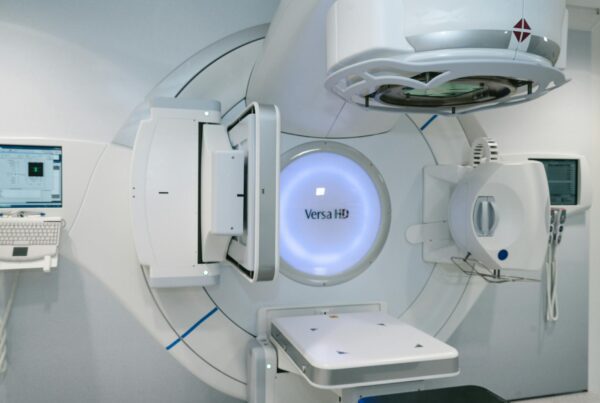
HDR afterloader (cobalt-60): minimum technical requirements
The technical specification calls for a remote-controlled afterloading system with ≥ 20 channels for intracavitary HDR brachytherapy using a cobalt-60 source with activity 74 GBq ±10% on delivery. The afterloader should automatically verify unique applicator connections and be easily manoeuvrable within the treatment room.
For safety and reproducibility, the requirements include precise double drives for a miniaturized cobalt-60 source and a dummy source, with continuous digital positioning, a pre-exposure routine dummy test run, and a catheter length check.
At the control console, the document is explicit about operational and governance features: network connection to the dedicated TPS; password-defined user access with restricted access to high-security data (for example, source strength); a log of user activity and the number of source transfers; a database of uniquely defined standard treatment plans for rigid applicator sets and line sources with automatic update of source dwell times, with plan editing access restricted and password-controlled; unique patient identification and plan preparation; status display including during power interruption; online treatment recording with a visual graphic display of progress; and hardcopy output of the full treatment protocol after treatment.
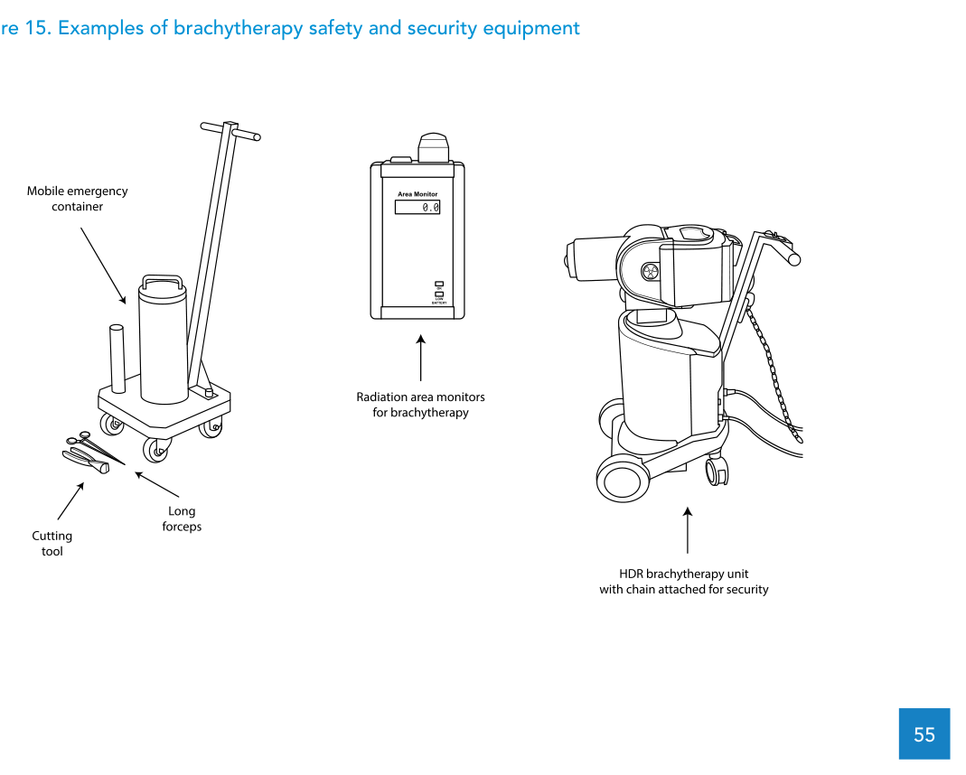
For power failures, the specification requires an internal battery or UPS to ensure safe retraction of the source or dummy. The emergency provisions include a crank for manual source retraction, long-handle forceps, and an emergency container with shielding sufficient to store up to 81 GBq cobalt-60 and large enough to fit the largest applicator.
On room-side safety infrastructure, the text includes an area monitoring system with audible and visible signals (treatment room and control panel), warning lights, facility access interlock, a patient intercommunication device, and two complete CCTV systems with pan/zoom/tilt. It also specifies a patient treatment table configuration that enables X-ray imaging, including a radiolucent tabletop and manoeuvrability to treat a patient in the seated position.
The applicator and accessory set, typically in multiple quantities depending on workload and case mix, includes CT-MR compatible sets (for example, Fletcher and ring sets), vaginal/rectal sets, and titanium intrauterine tubes with diameters 3.5 mm and 5.0 mm, plus accessories (for example, transfer tubes, markers and a sterilization box), a universal clamping device, and a reconstruction box for gynaecological applications.
On standards, the afterloader specification is anchored in IEC 60601-2-17:2013 and in requirements for sealed radioactive sources (ISO 2919:2012 and ISO 9978:1992), along with guidance on error and warning messages for radiotherapy software (IEC TR 63183:2019).
Safety, protection and source security: bunker and verification steps
The afterloader, including the source, is to be stored and operated in a concrete bunker. For shielding design, the text points to the methodology in IAEA Safety Reports Series No. 47 and emphasizes that floor, ceiling and wall shielding must be considered, together with local requirements for dose constraints and dose limits.
Typical brachytherapy suite layouts (treatment room, control room, preparation and recovery rooms) are referenced, and the room is framed as a controlled area under the International Basic Safety Standards. Source security measures are to be implemented in line with local regulations, including locking the afterloader when not in use, secure door access, and out-of-hours security for the radiotherapy department.
After installation, the document requires a comprehensive radiation survey in the vicinity of the treatment room to demonstrate compliance with local dose limits for staff and members of the public, using a calibrated survey meter. It also lists treatment-room features aimed at safety, protection and source security: an area radiation monitor, facility access interlock, an emergency storage container and forceps, beam-on illuminated signs, ionizing radiation trefoil warning signs, audio-visual communication between treatment and control rooms, emergency retract buttons in both locations, and security features to prevent unauthorized removal and sabotage.
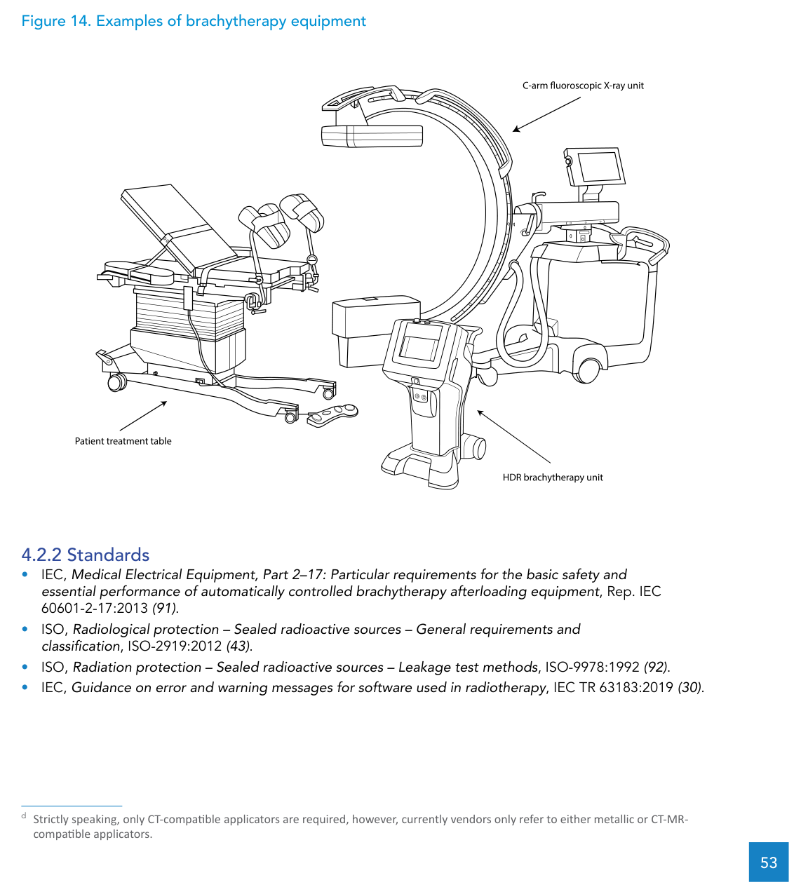
C-arm fluoroscopy: planar imaging for planning and verification
The C-arm fluoroscopic X-ray unit is described as a mobile X-ray source and imaging system on a rotating C-arm. It enables planar imaging of the brachytherapy patient in the treatment room with the applicator already inserted, with digital images that can be exported to a brachytherapy TPS.
The technical specification includes: a high-frequency generator with 40–110 kV potential and a tube with dual focal spots; fluoroscopic mode (foot switch and last-image-hold) and radiographic mode; a flat-panel detector at least 21 cm x 21 cm; dual high-resolution displays at least 18 inches with last-image-hold; orbital movement ≥ 120° (–30° to +90°); motor-driven vertical travel ≥ 40 cm; horizontal travel ≥ 20 cm; focus-to-image receptor distance ≥ 90 cm; free space ≥ 76 cm; a braking system for gantry control; a DICOM 3.0 interface (TPS or PACS); and hard-disk plus external image storage capability.
On radiation protection, the text notes that the bunker shielding for the brachytherapy source is expected to be sufficient for C-arm operation, but it still requires operator protection with a lead gown with thyroid collar during exposure and recommends that staff other than the operator be outside the room during C-arm use. The unit should also be included in routine quality control testing covering the X-ray system, mechanical features and safety features.
Ultrasound guidance: requirements including Package 2
Ultrasound is included as an imaging system used to guide and confirm placement of intracavitary applicators, with abdominal transducers identified as needed for applicator placement guidance. The specification calls for a mobile unit capable of 2D and M-mode, with two active transducer ports and two high-frequency convex transducers covering 2.0–5.0 MHz for trans-abdominal gynaecological examinations.
For Package 2, it adds two biplane transrectal transducers (sagittal and transverse) covering 3.0–12.0 MHz. The monitor should be at least 18 inches and display not less than 256 grey levels in 2D mode. The text also specifies a keyboard with one-button control, USB port and video output, onboard thermal printer and an A4 laser printer, measurement tools (length, height, width, angle, area and volume), image storage in a clinically useful format and resolution, and transfer capability using the DICOM standard, plus water soluble and hypoallergenic gel. For QA, stability of image quality per transducer and for the system overall is emphasized.
Brachytherapy TPS: reconstruction, optimization and transfer
The brachytherapy TPS is defined as software used to create brachytherapy treatment plans based on source dosimetric characteristics, applicator dimensions, patient images and permitted source positions and dwell times. The safety standard cited for planning systems is IEC 62083:2009.
The technical specification includes a networked workstation with a 23-inch monitor and significant storage capacity, with dose optimization based on points, planes or volumes using catheter and dwell positions obtained via reconstruction from isocentric, orthogonal and semi-orthogonal images. For imaging interoperability, it requires hardware, software and licenses that support DICOM-compliant image transfer from CT, MRI, and also from a conventional simulator or a C-arm fluoroscopic X-ray unit. A flatbed film scanner (or equivalent) is included to allow manual input of films or digitized images.
For consistency and security, the text calls for reference data sets (a library) for the source and for all applicators offered, plus hierarchical password-controlled access to source calibration, modelling parameters, the library of standard plans, and synchronization of source data with the treatment control panel. It also includes system manager software for database maintenance and archiving, a printer for A3/A4 output of isodose distributions and plan parameters, and software for automatic online transfer of patient and authorized plan data to the afterloader control panel. On QA, the document highlights regular testing of features and algorithm results, special attention to software upgrades, and confirming that current source strength is correctly reflected in the TPS.
If you also cover external beam workflows, you may find it useful to read the related article in this series: technical specifications for external beam radiotherapy (EBRT) equipment.
Dosimetry and quality control for HDR (Table 16)
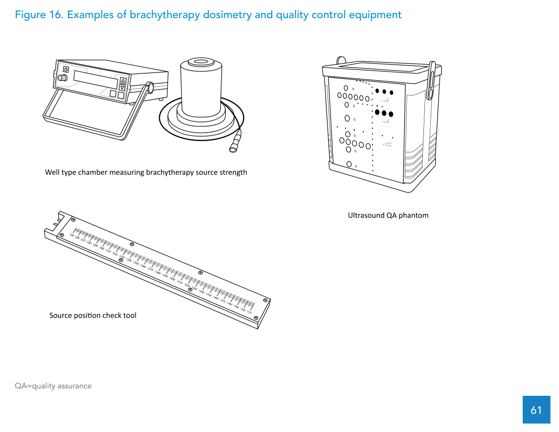
The document frames brachytherapy dosimetry around establishing the reference air kerma rate (RAKR) of the source and identifies the well-type ionization chamber as the preferred detector for this purpose. The table below lists HDR-specific dosimetry and QC equipment, including an ultrasound image quality phantom.
Table 16. Dosimetry and quality control equipment for HDR brachytherapy
The items, descriptions and comments are presented in HTML while preserving the required specifications and numeric values from the document.
| Item | Description | Comments |
|---|---|---|
| Well-type ionization chamber | Well-type ionization chamber for measuring source strength of HDR afterloader cobalt-60 or iridium-192 brachytherapy source, TNC or BNC connector, including calibration certificate, with adapter required specific to afterloader manufacturer and model. | Recalibration at an SSDL or PSDL is recommended every 2 years. |
| Triaxial cable | Triaxial extension cable at least 10 m in length, with TNC or BNC connectors. | Purchase of a spare cable is recommended, as these cables often fail with repeated handling or mishandling. |
| Electrometer | Reference-class single-channel electrometer compatible with a well-type chamber, with TNC or BNC connector. | Internal desiccator requires replacement at intervals depending on humidity. Preferably calibrate the electrometer together with the well-type chamber. |
| Thermometer | Glass (spirit) thermometer, 0°C–50°C, scale resolution 0.2° or less, including calibration certificate. | The use of mercury type rather than spirit type should not be allowed. |
| Barometer | Digital or aneroid barometer with 0.01 kPa resolution and calibration certificate, with a pressure reading range suitable for the elevation of the radiotherapy department location. | The pressure range is important at high elevations; pressure reduction is of the order of 1% per 80 m elevation. |
| Check source | Caesium-137 check device for well-type chamber, including adapter/holder. | Inclusion of radioactive material requires following the requirements of the local radiation regulator. |
| Film | Self-developing radiochromic film for brachytherapy dosimetry. | Consumable. |
| Source position check tool | Tool with cavity for the source, length scale in millimetres, and capability to incorporate radiochromic film for autoradiography. | Supplied by the afterloader vendor. |
| Ultrasound image quality phantom | Image quality phantom capable of tests of uniformity, geometric scale, contrast, resolution, sensitivity and dead zone; rubber-based, tissue-mimicking long-lasting material; combination of monofilament line targets and tissue-mimicking volumetric targets of various sizes; minimum line target diameter approximately 0.1 mm; optimized for display at the abdominal probe frequency range (2–5 MHz). | |
| Ultrasound QA phantom (transrectal imaging) | Tissue-equivalent phantom with complex shapes to check alignment of the electronic grid on the screen for correct horizontal/vertical distance measurements and to confirm axial and lateral resolution. Includes at least three calibration objects visible when turning the probe 60 degrees right or left, and capability to test depth of penetration, resolution, distance, area and volume measurements, as well as geometric consistency. | Should be considered when using transrectal ultrasound imaging for interstitial implants (Package 2). |
Source: WHO/IAEA Technical Specifications of Radiotherapy Equipment for Cancer Treatment (Table 16)
The text also notes that the check source is the radiation-emitting item within this group and should only be used by clinically qualified medical physicists, with secure storage and compliance with local rules for transport, use and storage of radioactive material. For the well-type chamber, recalibration every two years by an SSDL or PSDL is specified; between calibrations, stability checks can be performed using the check source.
WHO technical specifications: brachytherapy TPS (summary)
WHO, together with the IAEA, provides a template of technical specifications for the brachytherapy TPS. The table below summarizes core items from the annex, grouped by category for practical use in procurement, acceptance testing and implementation.
| Category | Item | Specification |
|---|---|---|
| Clinical purpose | Purpose of use | Preparation of patient treatment plans for brachytherapy. |
| Clinical purpose | Level of use | Hospital. |
| Clinical purpose | Department | Radiation Oncology Department. |
| Technical requirements | Software scope | Modules for image import/registration, contouring targets and organs at risk, planning source positions and dwell times, dose calculation, plan review/export, and source modelling. |
| Technical requirements | Workstation | Networked workstation with 23-inch monitor and significant storage capacity. |
| Technical requirements | Dose optimization | Optimization based on points, planes or volumes using catheter/dwell positions reconstructed from isocentric, orthogonal and semi-orthogonal images. |
| Imaging interoperability | DICOM inputs | DICOM-compliant image transfer from CT, MRI and conventional simulator or C-arm fluoroscopic X-ray unit. |
| Imaging interoperability | Manual input | Flatbed film scanner (or equivalent) for manual input of films or digitized images. |
| Data | Libraries | Reference data sets (library) for the source and all applicators offered. |
| Security | Password hierarchy | Hierarchical password-controlled access for source calibration, modelling parameters, standard plan library and synchronization of source data with the treatment control panel. |
| Operations | Database management | System manager software for database maintenance and archiving. |
| Outputs | Printing | Printer for A3/A4 output of isodose distributions and treatment plan parameters. |
| Clinical integration | Transfer to console | Software for automatic online transfer of patient and authorized plan data to the afterloader control panel. |
| Infrastructure | Power and AC | Single-phase electrical power and air-conditioning. |
| Infrastructure | Network availability | Network availability (pre-installation requirement). |
| Maintenance | Warranty | At least 12 months. |
| Maintenance | Updates | Software updates as required. |
| Maintenance | Service contract | Service contract including software upgrades and access to helpdesk. |
| Maintenance | Estimated lifespan | 5 years. |
| Safety/Standards | Specific standard | IEC 62083:2009. |
Source: WHO/IAEA Technical Specifications of Radiotherapy Equipment for Cancer Treatment (Annex 11)
To explore the other equipment and chapters in this series, return to the complete guide and follow the related links.